

Accutorr Plus Service Manual - Mindray
Accutorr Plus Service Manual - Mindray
Accutorr Plus Service Manual - Mindray

You also want an ePaper? Increase the reach of your titles
YUMPU automatically turns print PDFs into web optimized ePapers that Google loves.
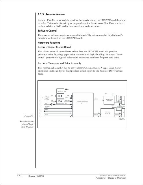
Figure 2-5<br />
Recorder Module<br />
Control Logic<br />
Block Diagram<br />
2.2.3 Recorder Module<br />
<strong>Accutorr</strong> <strong>Plus</strong> Recorder module provides the interface from the LED/CPU module to the<br />
recorder. This module is strictly an output device for the <strong>Accutorr</strong> <strong>Plus</strong>. Data is written<br />
to the module via DMA and is then routed out to the recorder.<br />
Software Control<br />
There are no software requirements on this board. The microcontroller for this board’s<br />
functions are located on the LED/CPU board.<br />
Hardware Functions<br />
Recorder Driver Circuit Board<br />
This circuit takes all control instructions from the LED/CPU board and provides<br />
printhead drive decoding, paper drive motor control logic decoding, printhead “home<br />
switch” position sensing and pulse width modulated oscillator for print head drive.<br />
Recorder Transport and Print Assembly<br />
This mechanical assembly has no active electronic components. A paper drive motor,<br />
print head shuttle and print head position sensor report to the Recorder Driver circuit<br />
board.<br />
2-20 Revised 12/20/00<br />
<strong>Accutorr</strong> <strong>Plus</strong> <strong>Service</strong> <strong>Manual</strong><br />
Chapter 2 - Theory of Operation


