

Accutorr Plus Service Manual - Mindray
Accutorr Plus Service Manual - Mindray
Accutorr Plus Service Manual - Mindray

Create successful ePaper yourself
Turn your PDF publications into a flip-book with our unique Google optimized e-Paper software.
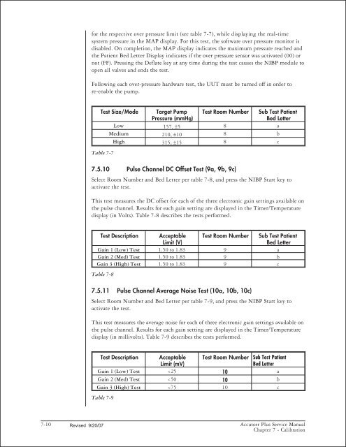
for the respective over pressure limit (see table 7-7), while displaying the real-time<br />
system pressure in the MAP display. For this test, the software over pressure monitor is<br />
disabled. On completion, the MAP display indicates the maximum pressure reached and<br />
the Patient Bed Letter Display indicates if the over pressure sensor was activated (00) or<br />
not (FF). Pressing the Deflate key at any time during the test causes the NIBP module to<br />
open all valves and ends the test.<br />
Following each over-pressure hardware test, the UUT must be turned off in order to<br />
re-enable the pump.<br />
Test Size/Mode Target Pump Test Room Number Sub Test Patient<br />
Pressure (mmHg)<br />
Bed Letter<br />
Low 157, 5 8 a<br />
Medium 210, 10 8 b<br />
High 315, 15 8 c<br />
Table 7-7<br />
7.5.10 Pulse Channel DC Offset Test (9a, 9b, 9c)<br />
Select Room Number and Bed Letter per table 7-8, and press the NIBP Start key to<br />
activate the test.<br />
This test measures the DC offset for each of the three electronic gain settings available on<br />
the pulse channel. Results for each gain setting are displayed in the Timer/Temperature<br />
display (in Volts). Table 7-8 describes the tests performed.<br />
Test Description Acceptable Test Room Number Sub Test Patient<br />
Limit (V)<br />
Bed Letter<br />
Gain 1 (Low) Test 1.50 to 1.83 9 a<br />
Gain 2 (Med) Test 1.50 to 1.83 9 b<br />
Gain 3 (High) Test 1.50 to 1.83 9 c<br />
Table 7-8<br />
7.5.11 Pulse Channel Average Noise Test (10a, 10b, 10c)<br />
Select Room Number and Bed Letter per table 7-9, and press the NIBP Start key to<br />
activate the test.<br />
This test measures the average noise for each of three electronic gain settings available on<br />
the pulse channel. Results for each gain setting are displayed in the Timer/Temperature<br />
display (in millivolts). Table 7-9 describes the tests performed.<br />
Test Description Acceptable Test Room Number Sub Test Patient<br />
Limit (mV)<br />
Bed Letter<br />
Gain 1 (Low) Test


