

Hydrovar Pump Controller Installation & Operation Manual
Hydrovar Pump Controller Installation & Operation Manual
Hydrovar Pump Controller Installation & Operation Manual

Create successful ePaper yourself
Turn your PDF publications into a flip-book with our unique Google optimized e-Paper software.
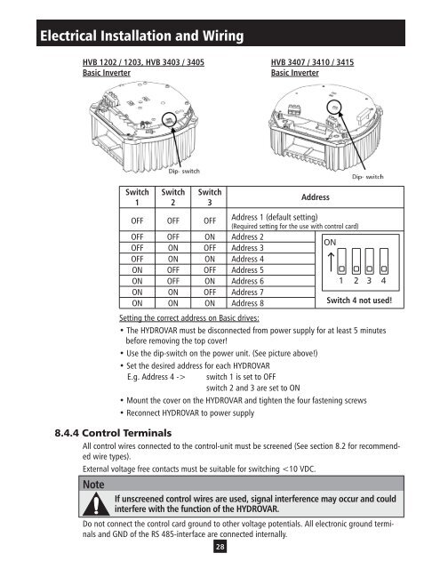
Electrical <strong>Installation</strong> and Wiring<br />
HVB 1202 / 1203, HVB 3403 / 3405 HVB 3407 / 3410 / 3415<br />
Basic Inverter Basic Inverter<br />
Switch Switch Switch<br />
1 2 3<br />
28<br />
Address<br />
OFF OFF OFF<br />
Address 1 (default setting)<br />
(Required setting for the use with control card)<br />
OFF<br />
OFF<br />
OFF<br />
ON<br />
ON<br />
OFF<br />
Address 2<br />
Address 3<br />
ON<br />
OFF ON ON Address 4<br />
ON OFF OFF Address 5<br />
ON OFF ON Address 6<br />
1 2 3 4<br />
ON<br />
ON<br />
ON<br />
ON<br />
OFF<br />
ON<br />
Address 7<br />
Address 8 Switch 4 not used!<br />
Setting the correct address on Basic drives:<br />
• The HYDROVAR must be disconnected from power supply for at least 5 minutes<br />
before removing the top cover!<br />
• Use the dip-switch on the power unit. (See picture above!)<br />
• Set the desired address for each HYDROVAR<br />
E.g. Address 4 -> switch 1 is set to OFF<br />
switch 2 and 3 are set to ON<br />
• Mount the cover on the HYDROVAR and tighten the four fastening screws<br />
• Reconnect HYDROVAR to power supply<br />
8.4.4 Control Terminals<br />
All control wires connected to the control-unit must be screened (See section 8.2 for recommended<br />
wire types).<br />
External voltage free contacts must be suitable for switching


