

Hydrovar Pump Controller Installation & Operation Manual
Hydrovar Pump Controller Installation & Operation Manual
Hydrovar Pump Controller Installation & Operation Manual

You also want an ePaper? Increase the reach of your titles
YUMPU automatically turns print PDFs into web optimized ePapers that Google loves.
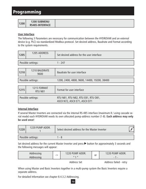
Programming<br />
1200<br />
User Interface<br />
1200 SUBMENU<br />
RS485-INTERFACE<br />
The following 3 Parameters are necessary for communication between the HYDROVAR and an external<br />
device (e.g. PLC) via standardized Modbus-protocol. Set desired address, Baudrate and Format according<br />
to the system requirements.<br />
1205<br />
1205 ADDRESS<br />
1<br />
Possible settings: 1 - 247<br />
1210<br />
1210 BAUDRATE<br />
9600<br />
Set desired address for the user interface<br />
Baudrate for user interface<br />
Possible settings: 1200, 2400, 4800, 9600, 14400, 19200, 38400<br />
1215<br />
1215 FORMAT<br />
RTU N81<br />
Format for user interface<br />
Possible settings: RTU N81, RTU N82, RTU E81, RTU O81,<br />
ASCII N72, ASCII E71, ASCII O71<br />
Internal Interface<br />
If several Master Inverters are connected via the internal RS-485 interface (maximum 8 / using cascade serial<br />
mode) each HYDROVAR needs its own allocated pump-address number (1-8). Each address may only<br />
be used once!<br />
1220<br />
1220 PUMP ADDR.<br />
1<br />
Possible settings: 1 - 8<br />
Select desired address for the Master Inverter<br />
Set desired address for the current Master Inverter and press button for approximately 3 seconds and<br />
the following messages will appear:<br />
Addressing<br />
1220 PUMP ADDR.<br />
1220 PUMP ADDR.<br />
-><br />
or<br />
Addressing * 1 * - 1 -<br />
Address Set Address failed - retry<br />
When using Master and Basic Inverters together in a multi-pump system the Basic Inverters require a<br />
separate address.<br />
For detailed Information see chapter 8.4.3.2 Addressing.<br />
70<br />
S


