A GEM Detector System for an Upgrade of the CMS Muon Endcaps
A GEM Detector System for an Upgrade of the CMS Muon Endcaps
A GEM Detector System for an Upgrade of the CMS Muon Endcaps

You also want an ePaper? Increase the reach of your titles
YUMPU automatically turns print PDFs into web optimized ePapers that Google loves.
3 Studies <strong>of</strong> small <strong>an</strong>d full-scale <strong>GEM</strong> prototypes<br />
3.1 Initial prototypes <strong>for</strong> choosing among MPGD technologies<br />
As <strong>the</strong> very first step <strong>of</strong> this project, small prototypes <strong>of</strong> two different MPGD types were characterized: one<br />
Micromegas [7] detector <strong>an</strong>d one Triple-<strong>GEM</strong> [8] detector. Both prototypes were produced with <strong>an</strong> active area <strong>of</strong><br />
10 cm×10 cm in <strong>the</strong> CERN EN-ICE surface treatment workshop <strong>an</strong>d were subsequently tested in <strong>the</strong> RD51 [4]<br />
lab <strong>of</strong> <strong>the</strong> CERN <strong>Detector</strong> Technology Group (DT). Using st<strong>an</strong>dard Ar/CO2 gas mixtures, <strong>the</strong> two detectors were<br />
characterized by measuring gain <strong>an</strong>d pulse height spectra with radioactive sources <strong>an</strong>d Cu x-rays from a generator.<br />
Their efficiency plateaus were measured <strong>an</strong>d <strong>the</strong> optimal operational voltages were determined.<br />
In October 2009, <strong>the</strong> two prototypes were put into a pion/muon test beam at <strong>the</strong> CERN SPS H4 beam line [9]. In<br />
this test, good detector per<strong>for</strong>m<strong>an</strong>ce was observed <strong>for</strong> <strong>the</strong> Triple-<strong>GEM</strong> while <strong>the</strong> Micromegas prototype showed a<br />
subst<strong>an</strong>tial number <strong>of</strong> discharges <strong>an</strong>d hence poorer data quality. The discharge probabilities <strong>of</strong> <strong>the</strong> two detectors<br />
were subsequently measured in <strong>the</strong> RD51 lab. For <strong>the</strong> Triple-<strong>GEM</strong> a probability <strong>of</strong> 10 −6 was measured <strong>for</strong> gains<br />
up to 2·10 4 , while <strong>the</strong> Micromegas was discharging with a probability <strong>of</strong> 10 −4 at a gain <strong>of</strong> less th<strong>an</strong> 2000. These<br />
results were consistent with previous MPGD studies. Based on <strong>the</strong>se findings <strong>an</strong>d given <strong>the</strong> existing expertise on<br />
<strong>GEM</strong>s within <strong>the</strong> research group, <strong>the</strong> Triple-<strong>GEM</strong> MPGD was selected <strong>for</strong> detailed fur<strong>the</strong>r studies.<br />
3.2 Triple-<strong>GEM</strong> prototypes<br />
<strong>GEM</strong> foils are made from 50µm thick kapton sheets with a 5µm copper cladding on both sides. The initial small<br />
10cm×10cm Triple-<strong>GEM</strong> was constructed using <strong>the</strong> st<strong>an</strong>dard double-mask technique <strong>for</strong> etching <strong>GEM</strong> foils. The<br />
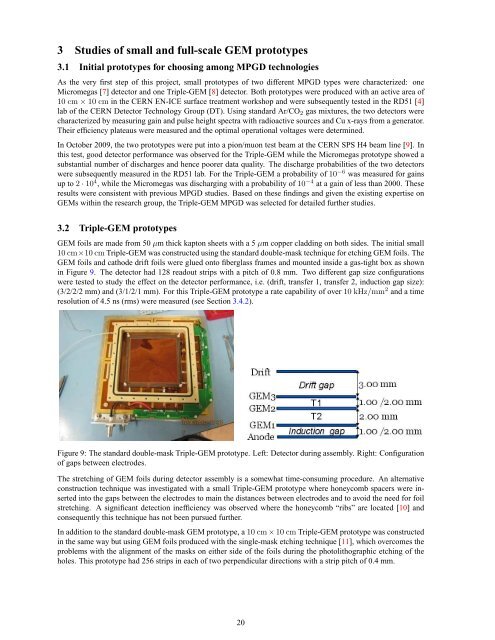
<strong>GEM</strong> foils <strong>an</strong>d cathode drift foils were glued onto fiberglass frames <strong>an</strong>d mounted inside a gas-tight box as shown<br />
in Figure 9. The detector had 128 readout strips with a pitch <strong>of</strong> 0.8 mm. Two different gap size configurations<br />
were tested to study <strong>the</strong> effect on <strong>the</strong> detector per<strong>for</strong>m<strong>an</strong>ce, i.e. (drift, tr<strong>an</strong>sfer 1, tr<strong>an</strong>sfer 2, induction gap size):<br />
(3/2/2/2 mm) <strong>an</strong>d (3/1/2/1 mm). For this Triple-<strong>GEM</strong> prototype a rate capability <strong>of</strong> over 10kHz/mm 2 <strong>an</strong>d a time<br />
resolution <strong>of</strong> 4.5 ns (rms) were measured (see Section 3.4.2).<br />
Figure 9: The st<strong>an</strong>dard double-mask Triple-<strong>GEM</strong> prototype. Left: <strong>Detector</strong> during assembly. Right: Configuration<br />
<strong>of</strong> gaps between electrodes.<br />
The stretching <strong>of</strong> <strong>GEM</strong> foils during detector assembly is a somewhat time-consuming procedure. An alternative<br />
construction technique was investigated with a small Triple-<strong>GEM</strong> prototype where honeycomb spacers were inserted<br />
into <strong>the</strong> gaps between <strong>the</strong> electrodes to main <strong>the</strong> dist<strong>an</strong>ces between electrodes <strong>an</strong>d to avoid <strong>the</strong> need <strong>for</strong> foil<br />
stretching. A signific<strong>an</strong>t detection inefficiency was observed where <strong>the</strong> honeycomb “ribs” are located [10] <strong>an</strong>d<br />
consequently this technique has not been pursued fur<strong>the</strong>r.<br />
In addition to <strong>the</strong> st<strong>an</strong>dard double-mask <strong>GEM</strong> prototype, a10cm×10cm Triple-<strong>GEM</strong> prototype was constructed<br />
in <strong>the</strong> same way but using <strong>GEM</strong> foils produced with <strong>the</strong> single-mask etching technique [11], which overcomes <strong>the</strong><br />
problems with <strong>the</strong> alignment <strong>of</strong> <strong>the</strong> masks on ei<strong>the</strong>r side <strong>of</strong> <strong>the</strong> foils during <strong>the</strong> photolithographic etching <strong>of</strong> <strong>the</strong><br />
holes. This prototype had 256 strips in each <strong>of</strong> two perpendicular directions with a strip pitch <strong>of</strong> 0.4 mm.<br />
20