A GEM Detector System for an Upgrade of the CMS Muon Endcaps
A GEM Detector System for an Upgrade of the CMS Muon Endcaps
A GEM Detector System for an Upgrade of the CMS Muon Endcaps

Create successful ePaper yourself
Turn your PDF publications into a flip-book with our unique Google optimized e-Paper software.
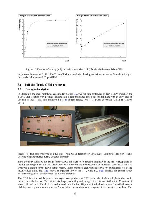
Figure 17: <strong>Detector</strong> efficiency (left) <strong>an</strong>d strip cluster size (right) <strong>for</strong> <strong>the</strong> single-mask Triple-<strong>GEM</strong>.<br />
to gains on <strong>the</strong> order <strong>of</strong> 3·10 4 . The Triple-<strong>GEM</strong> produced with <strong>the</strong> single-mask technique per<strong>for</strong>med similarly to<br />
<strong>the</strong> st<strong>an</strong>dard double-mask Triple-<strong>GEM</strong>.<br />
3.5 Full-size Triple-<strong>GEM</strong> prototype<br />
3.5.1 Prototype description<br />
In addition to <strong>the</strong> small prototypes described in Section 3.2, two full-size prototypes <strong>of</strong> Triple-<strong>GEM</strong> chambers <strong>for</strong><br />
a <strong>CMS</strong> GE1/1 station were produced <strong>an</strong>d studied. These prototypes have a trapezoidal shape with <strong>an</strong> active area <strong>of</strong><br />
990 mm×(220−455) mm as shown in Fig. 18 <strong>an</strong>d are labeled “GE1/1-I” (April 2010) <strong>an</strong>d “GE1/1-II” (March<br />
2011).<br />
Figure 18: The first prototype <strong>of</strong> a full-size Triple-<strong>GEM</strong> detector <strong>for</strong> <strong>CMS</strong>. Left: Completed detector. Right:<br />
Glueing <strong>of</strong> spacer frames during detector assembly.<br />
Their geometry followed <strong>the</strong> design <strong>for</strong> <strong>the</strong> RPCs that were to be installed originally in <strong>the</strong> ME1 endcap disks in<br />
<strong>the</strong> highest η region, i.e. RE1/1. In fact, <strong>the</strong> <strong>GEM</strong> detectors were embedded in <strong>an</strong> aluminum cover box similar to<br />
what was designed <strong>for</strong> <strong>the</strong> RPCs in that region. These chambers each would cover a 10 ◦ azimuthal sector <strong>of</strong> <strong>the</strong><br />
muon endcap disks. Fig. 19(a) shows <strong>an</strong> exploded view <strong>of</strong> GE1/1-I, while Fig. 19(b) displays <strong>the</strong> general layout<br />
<strong>an</strong>d different gap size configurations <strong>of</strong> <strong>the</strong> two prototypes.<br />
The <strong>GEM</strong> foils <strong>for</strong> both large-area prototypes were produced at CERN using <strong>the</strong> single-mask photolithographic<br />
process described above. To limit <strong>the</strong> discharge probability <strong>an</strong>d strength, <strong>the</strong> foils are divided into 35 sectors <strong>of</strong><br />
about 100 cm 2 each. The drift electrodes, made <strong>of</strong> a thicker 300 µm kapton foil with a solid 5 µm thick copper<br />
cladding, were glued directly onto <strong>the</strong> 3 mm thick bottom aluminum baseplate <strong>of</strong> <strong>the</strong> detector cover box. The<br />
25