A GEM Detector System for an Upgrade of the CMS Muon Endcaps
A GEM Detector System for an Upgrade of the CMS Muon Endcaps
A GEM Detector System for an Upgrade of the CMS Muon Endcaps

You also want an ePaper? Increase the reach of your titles
YUMPU automatically turns print PDFs into web optimized ePapers that Google loves.
7 Cooling, gas <strong>an</strong>d cabling services<br />
7.1 Gas<br />
The <strong>GEM</strong> detector system <strong>for</strong> <strong>the</strong> <strong>CMS</strong> experiment has a total volume <strong>of</strong> about 3.4m 3 . The chambers are operated<br />
with a three component gas mixture made <strong>of</strong> Ar/CO2/CF4 (45:15:40). The basic function <strong>of</strong> <strong>the</strong> gas system is<br />
to mix <strong>the</strong> three components in <strong>the</strong> appropriate proportions <strong>an</strong>d to distribute <strong>the</strong> gas mixture into <strong>the</strong> individual<br />
chambers. The expected flow regime is 5 volume ch<strong>an</strong>ges per day equivalent to about 700 nl/h. The gas system<br />
<strong>for</strong> <strong>the</strong> <strong>GEM</strong> detector will re-use part <strong>of</strong> <strong>the</strong> infrastructure as <strong>the</strong>y were <strong>for</strong>eseen <strong>for</strong> <strong>the</strong> innermost RPC end-cap<br />
station, in particularly <strong>the</strong> distribution racks located in <strong>the</strong> experimental cavern. The detector volume, <strong>the</strong> required<br />
gas flow <strong>an</strong>d <strong>the</strong> use <strong>of</strong> a relatively expensive gas mixture make a closed-loop circulation system highly favorable.<br />
The system proposed consists <strong>of</strong> several modules, which are designed using <strong>the</strong> st<strong>an</strong>dard adopted in all <strong>the</strong> gas<br />
system <strong>for</strong> <strong>the</strong> LHC experiments. The gas system will be running on PLC <strong>an</strong>d it will be controlled/monitored<br />
using <strong>the</strong> st<strong>an</strong>dard PVSS 4) interface.<br />
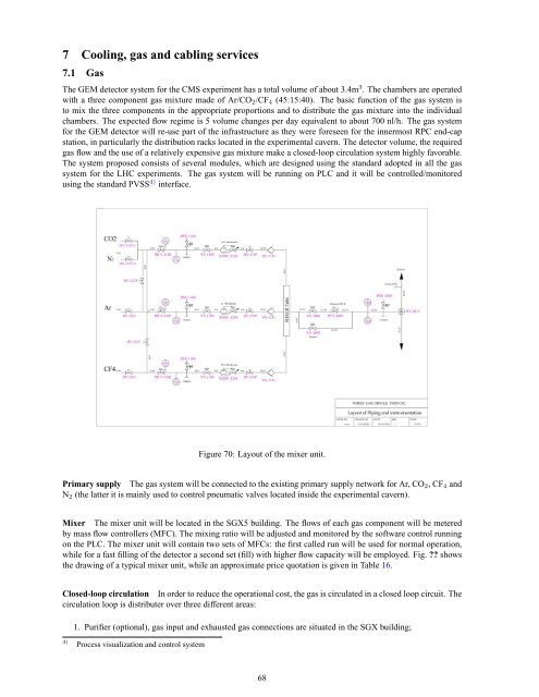
Figure 70: Layout <strong>of</strong> <strong>the</strong> mixer unit.<br />
Primary supply The gas system will be connected to <strong>the</strong> existing primary supply network <strong>for</strong> Ar, CO2, CF4 <strong>an</strong>d<br />
N2 (<strong>the</strong> latter it is mainly used to control pneumatic valves located inside <strong>the</strong> experimental cavern).<br />
Mixer The mixer unit will be located in <strong>the</strong> SGX5 building. The flows <strong>of</strong> each gas component will be metered<br />
by mass flow controllers (MFC). The mixing ratio will be adjusted <strong>an</strong>d monitored by <strong>the</strong> s<strong>of</strong>tware control running<br />
on <strong>the</strong> PLC. The mixer unit will contain two sets <strong>of</strong> MFCs: <strong>the</strong> first called run will be used <strong>for</strong> normal operation,<br />
while <strong>for</strong> a fast filling <strong>of</strong> <strong>the</strong> detector a second set (fill) with higher flow capacity will be employed. Fig. ?? shows<br />
<strong>the</strong> drawing <strong>of</strong> a typical mixer unit, while <strong>an</strong> approximate price quotation is given in Table 16.<br />
Closed-loop circulation In order to reduce <strong>the</strong> operational cost, <strong>the</strong> gas is circulated in a closed loop circuit. The<br />
circulation loop is distributer over three different areas:<br />
1. Purifier (optional), gas input <strong>an</strong>d exhausted gas connections are situated in <strong>the</strong> SGX building;<br />
4) Process visualization <strong>an</strong>d control system<br />
68