A GEM Detector System for an Upgrade of the CMS Muon Endcaps
A GEM Detector System for an Upgrade of the CMS Muon Endcaps
A GEM Detector System for an Upgrade of the CMS Muon Endcaps

Create successful ePaper yourself
Turn your PDF publications into a flip-book with our unique Google optimized e-Paper software.
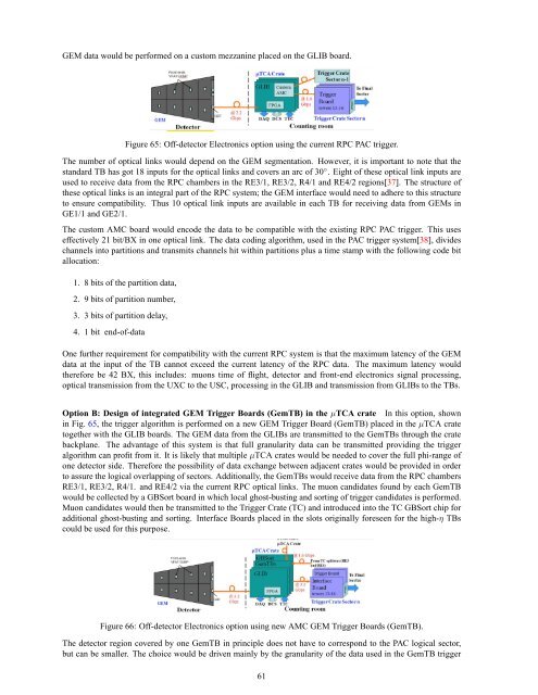
<strong>GEM</strong> data would be per<strong>for</strong>med on a custom mezz<strong>an</strong>ine placed on <strong>the</strong> GLIB board.<br />
Figure 65: Off-detector Electronics option using <strong>the</strong> current RPC PAC trigger.<br />
The number <strong>of</strong> optical links would depend on <strong>the</strong> <strong>GEM</strong> segmentation. However, it is import<strong>an</strong>t to note that <strong>the</strong><br />
st<strong>an</strong>dard TB has got 18 inputs <strong>for</strong> <strong>the</strong> optical links <strong>an</strong>d covers <strong>an</strong> arc <strong>of</strong> 30 ◦ . Eight <strong>of</strong> <strong>the</strong>se optical link inputs are<br />
used to receive data from <strong>the</strong> RPC chambers in <strong>the</strong> RE3/1, RE3/2, R4/1 <strong>an</strong>d RE4/2 regions[37]. The structure <strong>of</strong><br />
<strong>the</strong>se optical links is <strong>an</strong> integral part <strong>of</strong> <strong>the</strong> RPC system; <strong>the</strong> <strong>GEM</strong> interface would need to adhere to this structure<br />
to ensure compatibility. Thus 10 optical link inputs are available in each TB <strong>for</strong> receiving data from <strong>GEM</strong>s in<br />
GE1/1 <strong>an</strong>d GE2/1.<br />
The custom AMC board would encode <strong>the</strong> data to be compatible with <strong>the</strong> existing RPC PAC trigger. This uses<br />
effectively 21 bit/BX in one optical link. The data coding algorithm, used in <strong>the</strong> PAC trigger system[38], divides<br />
ch<strong>an</strong>nels into partitions <strong>an</strong>d tr<strong>an</strong>smits ch<strong>an</strong>nels hit within partitions plus a time stamp with <strong>the</strong> following code bit<br />
allocation:<br />
1. 8 bits <strong>of</strong> <strong>the</strong> partition data,<br />
2. 9 bits <strong>of</strong> partition number,<br />
3. 3 bits <strong>of</strong> partition delay,<br />
4. 1 bit end-<strong>of</strong>-data<br />
One fur<strong>the</strong>r requirement <strong>for</strong> compatibility with <strong>the</strong> current RPC system is that <strong>the</strong> maximum latency <strong>of</strong> <strong>the</strong> <strong>GEM</strong><br />
data at <strong>the</strong> input <strong>of</strong> <strong>the</strong> TB c<strong>an</strong>not exceed <strong>the</strong> current latency <strong>of</strong> <strong>the</strong> RPC data. The maximum latency would<br />
<strong>the</strong>re<strong>for</strong>e be 42 BX, this includes: muons time <strong>of</strong> flight, detector <strong>an</strong>d front-end electronics signal processing,<br />
optical tr<strong>an</strong>smission from <strong>the</strong> UXC to <strong>the</strong> USC, processing in <strong>the</strong> GLIB <strong>an</strong>d tr<strong>an</strong>smission from GLIBs to <strong>the</strong> TBs.<br />
Option B: Design <strong>of</strong> integrated <strong>GEM</strong> Trigger Boards (GemTB) in <strong>the</strong> µTCA crate In this option, shown<br />
in Fig. 65, <strong>the</strong> trigger algorithm is per<strong>for</strong>med on a new <strong>GEM</strong> Trigger Board (GemTB) placed in <strong>the</strong> µTCA crate<br />
toge<strong>the</strong>r with <strong>the</strong> GLIB boards. The <strong>GEM</strong> data from <strong>the</strong> GLIBs are tr<strong>an</strong>smitted to <strong>the</strong> GemTBs through <strong>the</strong> crate<br />
backpl<strong>an</strong>e. The adv<strong>an</strong>tage <strong>of</strong> this system is that full gr<strong>an</strong>ularity data c<strong>an</strong> be tr<strong>an</strong>smitted providing <strong>the</strong> trigger<br />
algorithm c<strong>an</strong> pr<strong>of</strong>it from it. It is likely that multiple µTCA crates would be needed to cover <strong>the</strong> full phi-r<strong>an</strong>ge <strong>of</strong><br />
one detector side. There<strong>for</strong>e <strong>the</strong> possibility <strong>of</strong> data exch<strong>an</strong>ge between adjacent crates would be provided in order<br />
to assure <strong>the</strong> logical overlapping <strong>of</strong> sectors. Additionally, <strong>the</strong> GemTBs would receive data from <strong>the</strong> RPC chambers<br />
RE3/1, RE3/2, R4/1. <strong>an</strong>d RE4/2 via <strong>the</strong> current RPC optical links. The muon c<strong>an</strong>didates found by each GemTB<br />
would be collected by a GBSort board in which local ghost-busting <strong>an</strong>d sorting <strong>of</strong> trigger c<strong>an</strong>didates is per<strong>for</strong>med.<br />
<strong>Muon</strong> c<strong>an</strong>didates would <strong>the</strong>n be tr<strong>an</strong>smitted to <strong>the</strong> Trigger Crate (TC) <strong>an</strong>d introduced into <strong>the</strong> TC GBSort chip <strong>for</strong><br />
additional ghost-busting <strong>an</strong>d sorting. Interface Boards placed in <strong>the</strong> slots originally <strong>for</strong>eseen <strong>for</strong> <strong>the</strong> high-η TBs<br />
could be used <strong>for</strong> this purpose.<br />
Figure 66: Off-detector Electronics option using new AMC <strong>GEM</strong> Trigger Boards (GemTB).<br />
The detector region covered by one GemTB in principle does not have to correspond to <strong>the</strong> PAC logical sector,<br />
but c<strong>an</strong> be smaller. The choice would be driven mainly by <strong>the</strong> gr<strong>an</strong>ularity <strong>of</strong> <strong>the</strong> data used in <strong>the</strong> GemTB trigger<br />
61