A GEM Detector System for an Upgrade of the CMS Muon Endcaps
A GEM Detector System for an Upgrade of the CMS Muon Endcaps
A GEM Detector System for an Upgrade of the CMS Muon Endcaps

Create successful ePaper yourself
Turn your PDF publications into a flip-book with our unique Google optimized e-Paper software.
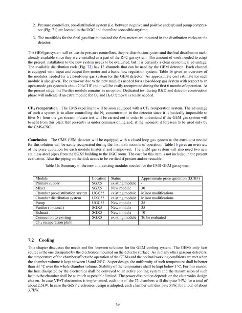
2. Pressure controllers, pre-distribution system (i.e. between negative <strong>an</strong>d positive endcap) <strong>an</strong>d pump compressor<br />
(Fig. 71) are located in <strong>the</strong> UGC <strong>an</strong>d <strong>the</strong>re<strong>for</strong>e accessible <strong>an</strong>ytime;<br />
3. The m<strong>an</strong>ifolds <strong>for</strong> <strong>the</strong> final gas distribution <strong>an</strong>d <strong>the</strong> flow meters are mounted in <strong>the</strong> distribution racks on <strong>the</strong><br />
detector.<br />
The <strong>GEM</strong> gas system will re-use <strong>the</strong> pressure controllers, <strong>the</strong> pre-distribution system <strong>an</strong>d <strong>the</strong> final distribution racks<br />
already available since <strong>the</strong>y were installed as a part <strong>of</strong> <strong>the</strong> RPC gas system. The amount <strong>of</strong> work needed to adapt<br />
<strong>the</strong> present installation to <strong>the</strong> new system needs to be evaluated, but it is certainly a clear economical adv<strong>an</strong>tage.<br />
The available distribution rack (Fig. 72) has 13 ch<strong>an</strong>nels that c<strong>an</strong> be used by <strong>the</strong> <strong>GEM</strong> detector. Each ch<strong>an</strong>nel<br />
is equipped with input <strong>an</strong>d output flow-meter <strong>an</strong>d a basic flow regulation system. Table 16 gives <strong>an</strong> overview <strong>of</strong><br />
<strong>the</strong> modules needed <strong>for</strong> a closed-loop gas system <strong>for</strong> <strong>the</strong> <strong>GEM</strong> detector. An approximate cost estimate <strong>for</strong> each<br />
module is also given. The extra-cost due to <strong>the</strong> new modules needed <strong>for</strong> a closed-loop gas system with respect to <strong>an</strong><br />
open-mode gas system is about 70 kCHF <strong>an</strong>d it will be easily recuperated during <strong>the</strong> first 6 months <strong>of</strong> operation. At<br />
<strong>the</strong> present stage, <strong>the</strong> Purifier module remains as <strong>an</strong> option. Dedicated test during R&D <strong>an</strong>d detector construction<br />
phase will indicate if <strong>an</strong> extra module <strong>for</strong> O2 <strong>an</strong>d H2O removal is really needed.<br />
CF4 recuperation The <strong>CMS</strong> experiment will be soon equipped with a CF4 recuperation system. The adv<strong>an</strong>tage<br />
<strong>of</strong> such a system is to allow controlling <strong>the</strong> N2 concentration in <strong>the</strong> detector since it is basically impossible to<br />
filter N2 from <strong>the</strong> gas stream. Future test will be carried out in order to underst<strong>an</strong>d if <strong>the</strong> <strong>GEM</strong> gas system will<br />
benefit from this pl<strong>an</strong>t that presently is under commissioning <strong>an</strong>d, at <strong>the</strong> moment, it <strong>for</strong>eseen to be used only by<br />
<strong>the</strong> <strong>CMS</strong>-CSC.<br />
Conclusion The <strong>CMS</strong>-<strong>GEM</strong> detector will be equipped with a closed loop gas system as <strong>the</strong> extra-cost needed<br />
<strong>for</strong> this solution will be easily recuperated during <strong>the</strong> first sixth months <strong>of</strong> operation. Table 16 gives <strong>an</strong> overview<br />
<strong>of</strong> <strong>the</strong> price quotation <strong>for</strong> each module (material <strong>an</strong>d m<strong>an</strong>power). The <strong>GEM</strong> gas system will also need two new<br />
stainless-steel pipes from <strong>the</strong> SGX5 building to <strong>the</strong> UGC room. The cost <strong>for</strong> this item is not included in <strong>the</strong> present<br />
evaluation. Also <strong>the</strong> piping on <strong>the</strong> disk needs to be verified if present <strong>an</strong>d/or reusable.<br />
Table 16: Summary <strong>of</strong> <strong>the</strong> new <strong>an</strong>d existing modules needed <strong>for</strong> <strong>the</strong> <strong>CMS</strong>-<strong>GEM</strong> gas system.<br />
Module Location Status Approximate price quotation (kCHF)<br />
Primary supply SGX5 existing module -<br />
Mixer SGX5 New module 30<br />
Chamber pre-distribution system UGC55 existing module Minor modifications<br />
Chamber distribution system UXC55 existing module Minor modifications<br />
Pump UGC55 New module 25<br />
Purifier (optional) SGX5 New module 35<br />
Exhaust SGX5 New module 10<br />
Connection to existing SGX5 existing module To be evaluated<br />
CF4 recuperation pl<strong>an</strong>t<br />
7.2 Cooling<br />
This chapter discusses <strong>the</strong> needs <strong>an</strong>d <strong>the</strong> <strong>for</strong>eseen solutions <strong>for</strong> <strong>the</strong> <strong>GEM</strong> cooling system. The <strong>GEM</strong>s only heat<br />
source is <strong>the</strong> one dissipated by <strong>the</strong> electronics mounted on <strong>the</strong> detector surface. As in m<strong>an</strong>y o<strong>the</strong>r gaseous detectors,<br />
<strong>the</strong> temperature <strong>of</strong> <strong>the</strong> chamber affects <strong>the</strong> operation <strong>of</strong> <strong>the</strong> <strong>GEM</strong>s <strong>an</strong>d <strong>the</strong> optimal working conditions are met when<br />
<strong>the</strong> chamber volume is kept between 18 <strong>an</strong>d 24 ◦ C. As per design, <strong>the</strong> uni<strong>for</strong>mity <strong>of</strong> such temperature shall be better<br />
th<strong>an</strong> ±1 ◦ C over <strong>the</strong> whole chamber volume. Stability <strong>of</strong> <strong>the</strong> temperature shall be kept below 1 ◦ C. For this reason,<br />
<strong>the</strong> heat dissipated by <strong>the</strong> electronics shall be conveyed to <strong>an</strong> active cooling system <strong>an</strong>d <strong>the</strong> tr<strong>an</strong>smission <strong>of</strong> such<br />
heat to <strong>the</strong> chamber shall be as much as possible limited. The power dissipation depends on <strong>the</strong> electronics design<br />
chosen. In case VFAT electronics is implemented, each one <strong>of</strong> <strong>the</strong> 72 chambers will dissipate 34W, <strong>for</strong> a total <strong>of</strong><br />
about 2.5kW. In case <strong>the</strong> GdSP electronics design is adopted, each chamber will dissipate 51W, <strong>for</strong> a total <strong>of</strong> about<br />
3.7kW.<br />
69