A GEM Detector System for an Upgrade of the CMS Muon Endcaps
A GEM Detector System for an Upgrade of the CMS Muon Endcaps
A GEM Detector System for an Upgrade of the CMS Muon Endcaps

Create successful ePaper yourself
Turn your PDF publications into a flip-book with our unique Google optimized e-Paper software.
(a)<br />
(b)<br />
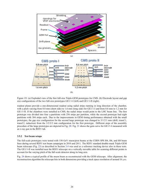
Figure 19: (a) Exploded view <strong>of</strong> <strong>the</strong> first full-size Triple-<strong>GEM</strong> prototypes <strong>for</strong> <strong>CMS</strong>. (b) Electrode layout <strong>an</strong>d gap<br />
size configurations <strong>of</strong> <strong>the</strong> two full-size prototypes GE1/1-I (left) <strong>an</strong>d GE1/1-II (right).<br />
readout pl<strong>an</strong>es provide a one-dimensional readout using radial strips running in long direction <strong>of</strong> <strong>the</strong> chamber,<br />
with a pitch varying from 0.8 mm (short side) to 1.6 mm (long side) <strong>for</strong> GE1/1-I <strong>an</strong>d from 0.6 mm to 1.2 mm <strong>for</strong><br />
GE1/1-II. If <strong>the</strong> chambers were installed in <strong>CMS</strong>, <strong>the</strong> radial strips would point to <strong>the</strong> LHC beam line. The first<br />
prototype was divided into four η-partitions with 256 strips per partition, while <strong>the</strong> second prototype had eight<br />
partitions with 384 strips each. Due to <strong>the</strong> improvements in <strong>GEM</strong> timing per<strong>for</strong>m<strong>an</strong>ce obtained with <strong>the</strong> small<br />
prototypes, <strong>the</strong> gap size configuration <strong>for</strong> <strong>the</strong> second large prototype was ch<strong>an</strong>ged to 3/1/2/1 mm (drift, tr<strong>an</strong>sf.1,<br />
tr<strong>an</strong>sf.2, induction) from <strong>the</strong> 3/2/2/2 mm configuration <strong>for</strong> <strong>the</strong> first prototype. Different steps <strong>of</strong> <strong>the</strong> assembly<br />
procedure <strong>of</strong> <strong>the</strong> large prototypes are depicted in Fig. 20. Fig. 21 shows <strong>the</strong> gain curve <strong>for</strong> GE1/1-I measured with<br />
<strong>an</strong> x-ray gun in <strong>the</strong> RD51 lab.<br />
3.5.2 Test beam setups<br />
The full-scale prototypes were tested with 150 GeV muon/pion beams at <strong>the</strong> CERN SPS H4, H6, <strong>an</strong>d H8 beam<br />
lines during several RD51 test beam campaigns in 2010 <strong>an</strong>d 2011. The RD51 st<strong>an</strong>dard double-mask Triple-<strong>GEM</strong><br />
beam telescope (Fig. 23) as described in Section 3.4 was used as a reference tracking device also in <strong>the</strong>se tests.<br />
The GE1/1-II was installed near <strong>the</strong> RD51 telescope on a vertically movable table <strong>for</strong> sc<strong>an</strong>ning different points to<br />
account <strong>for</strong> <strong>the</strong> varying pitch <strong>of</strong> <strong>the</strong> full-scale detector along its long axis.<br />
Fig. 24 shows a typical pr<strong>of</strong>ile <strong>of</strong> <strong>the</strong> muon beam as reconstructed with <strong>the</strong> <strong>GEM</strong> telescope. After alignment, <strong>the</strong><br />
reconstruction algorithm fits telescope hits in both dimensions providing a track space resolution <strong>of</strong> around50 µm.<br />
26