A GEM Detector System for an Upgrade of the CMS Muon Endcaps
A GEM Detector System for an Upgrade of the CMS Muon Endcaps
A GEM Detector System for an Upgrade of the CMS Muon Endcaps

You also want an ePaper? Increase the reach of your titles
YUMPU automatically turns print PDFs into web optimized ePapers that Google loves.
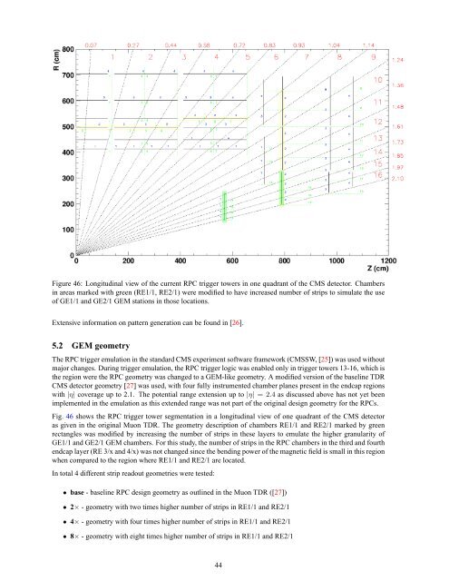
Figure 46: Longitudinal view <strong>of</strong> <strong>the</strong> current RPC trigger towers in one quadr<strong>an</strong>t <strong>of</strong> <strong>the</strong> <strong>CMS</strong> detector. Chambers<br />
in areas marked with green (RE1/1, RE2/1) were modified to have increased number <strong>of</strong> strips to simulate <strong>the</strong> use<br />
<strong>of</strong> GE1/1 <strong>an</strong>d GE2/1 <strong>GEM</strong> stations in those locations.<br />
Extensive in<strong>for</strong>mation on pattern generation c<strong>an</strong> be found in [26].<br />
5.2 <strong>GEM</strong> geometry<br />
The RPC trigger emulation in <strong>the</strong> st<strong>an</strong>dard <strong>CMS</strong> experiment s<strong>of</strong>tware framework (<strong>CMS</strong>SW, [25]) was used without<br />
major ch<strong>an</strong>ges. During trigger emulation, <strong>the</strong> RPC trigger logic was enabled only in trigger towers 13-16, which is<br />
<strong>the</strong> region were <strong>the</strong> RPC geometry was ch<strong>an</strong>ged to a <strong>GEM</strong>-like geometry. A modified version <strong>of</strong> <strong>the</strong> baseline TDR<br />
<strong>CMS</strong> detector geometry [27] was used, with four fully instrumented chamber pl<strong>an</strong>es present in <strong>the</strong> endcap regions<br />
with |η| coverage up to 2.1. The potential r<strong>an</strong>ge extension up to |η| = 2.4 as discussed above has not yet been<br />
implemented in <strong>the</strong> emulation as this extended r<strong>an</strong>ge was not part <strong>of</strong> <strong>the</strong> original design geometry <strong>for</strong> <strong>the</strong> RPCs.<br />
Fig. 46 shows <strong>the</strong> RPC trigger tower segmentation in a longitudinal view <strong>of</strong> one quadr<strong>an</strong>t <strong>of</strong> <strong>the</strong> <strong>CMS</strong> detector<br />
as given in <strong>the</strong> original <strong>Muon</strong> TDR. The geometry description <strong>of</strong> chambers RE1/1 <strong>an</strong>d RE2/1 marked by green<br />
rect<strong>an</strong>gles was modified by increasing <strong>the</strong> number <strong>of</strong> strips in <strong>the</strong>se layers to emulate <strong>the</strong> higher gr<strong>an</strong>ularity <strong>of</strong><br />
GE1/1 <strong>an</strong>d GE2/1 <strong>GEM</strong> chambers. For this study, <strong>the</strong> number <strong>of</strong> strips in <strong>the</strong> RPC chambers in <strong>the</strong> third <strong>an</strong>d fourth<br />
endcap layer (RE 3/x <strong>an</strong>d 4/x) was not ch<strong>an</strong>ged since <strong>the</strong> bending power <strong>of</strong> <strong>the</strong> magnetic field is small in this region<br />
when compared to <strong>the</strong> region where RE1/1 <strong>an</strong>d RE2/1 are located.<br />
In total 4 different strip readout geometries were tested:<br />
• base - baseline RPC design geometry as outlined in <strong>the</strong> <strong>Muon</strong> TDR ([27])<br />
• 2× - geometry with two times higher number <strong>of</strong> strips in RE1/1 <strong>an</strong>d RE2/1<br />
• 4× - geometry with four times higher number <strong>of</strong> strips in RE1/1 <strong>an</strong>d RE2/1<br />
• 8× - geometry with eight times higher number <strong>of</strong> strips in RE1/1 <strong>an</strong>d RE2/1<br />
44