Protocols for Secure Communication in Wireless Sensor Networks
Protocols for Secure Communication in Wireless Sensor Networks
Protocols for Secure Communication in Wireless Sensor Networks

You also want an ePaper? Increase the reach of your titles
YUMPU automatically turns print PDFs into web optimized ePapers that Google loves.
162 Chapter 6. Integrity-Preserv<strong>in</strong>g <strong>Communication</strong>s<br />
6.2.1 Protocol Description<br />
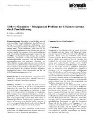
Consider the basic l<strong>in</strong>ear graph <strong>in</strong> figure 6.1 represent<strong>in</strong>g a simple sensor network.<br />
The solid edges between adjacent vertices represent physical communication<br />
l<strong>in</strong>ks that are used <strong>for</strong> transmitt<strong>in</strong>g messages. This communication graph<br />
is obta<strong>in</strong>ed, <strong>for</strong> example, by construct<strong>in</strong>g the rout<strong>in</strong>g graph used <strong>for</strong> geographic<br />
rout<strong>in</strong>g protocols such as GPSR [91]. For construct<strong>in</strong>g such a graph, certa<strong>in</strong><br />
edges are removed from the full connectivity graph, which conta<strong>in</strong>s <strong>in</strong><strong>for</strong>mation<br />
about which nodes are reachable from which other nodes. This could mean<br />
that, <strong>in</strong> pr<strong>in</strong>ciple, S1 may be able to send a message directly to S3. However, <strong>for</strong><br />
various reasons this l<strong>in</strong>k is not used. 1 Thus, S2 is a one-hop neighbour, while<br />
S3 is a two-hop neighbour of S1.<br />
S 1<br />
S 2 S 3 S 4<br />
Figure 6.1: A simple communication graph with <strong>in</strong>terleaved security relationships<br />
The dashed edges represent pairwise shared keys. Together with the vertices,<br />
they <strong>for</strong>m the authentication graph of the network. In the example, each<br />
node has a shared key with each node with<strong>in</strong> its two-hop neighbourhood, i.e.<br />
with all of its one-hop and two-hop neighbours. The key shared between nodes<br />
Si and S j will be denoted as Ki j = Kji. It is relatively straight<strong>for</strong>ward to set up<br />
such a sett<strong>in</strong>g us<strong>in</strong>g the techniques described <strong>in</strong> chapter 4.<br />
Whenever a message is <strong>for</strong>warded along a communication path, it is be<strong>in</strong>g<br />
authenticated us<strong>in</strong>g these keys. There are two cases we have to consider,<br />
message creation and message relay<strong>in</strong>g.<br />
Message creation When a message is generated from scratch, the source node<br />
creates k MACs targeted at the subsequent nodes on the path. As each of these<br />
nodes has a shared key with the source of the message, the authenticity of the<br />
message can be directly verified. For the first k hops on a path we can there<strong>for</strong>e<br />
speak of message authentication. If any of the first k−1 nodes tampers with the<br />
message, the follow<strong>in</strong>g node will detect the manipulation based on the MAC<br />
from the source.<br />
1 One of the reasons is energy efficiency. When transmitt<strong>in</strong>g a message from S1 to S3 via S2, both S1 and S2<br />
can reduce their transmission power. In total, this saves energy compared to S1 directly send<strong>in</strong>g to S3 with higher<br />
signal strength. Another reason is that geographic rout<strong>in</strong>g requires a planar communication graph.