Repair Manual Mobile Generator - Wacker Neuson
Repair Manual Mobile Generator - Wacker Neuson
Repair Manual Mobile Generator - Wacker Neuson

You also want an ePaper? Increase the reach of your titles
YUMPU automatically turns print PDFs into web optimized ePapers that Google loves.
Theory of Operation <strong>Mobile</strong> <strong>Generator</strong><br />
<strong>Wacker</strong> <strong>Neuson</strong> generators are designed to accommodate various<br />
loads and multiple power factors. Power factor is the relationship<br />
between power supplied to the load (referred to as apparent power in<br />
kVA) and true power (power used by the load (kW). It is expressed<br />
mathematically by the equation: power factor = true power ÷ apparent<br />
power. The power factor is determined by the type of load—inductive<br />
or resistive. In resistive loads, such as heaters, the power factor is typically<br />
1. In inductive loads, such as motors and transformers, the<br />
power factor is always less than 1. In inductive loads, a portion of the<br />
supplied power is converted to a magnetic field and not used by the<br />
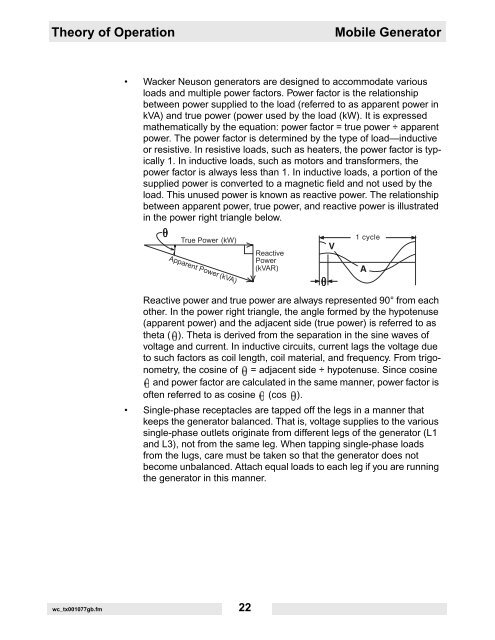
load. This unused power is known as reactive power. The relationship<br />
between apparent power, true power, and reactive power is illustrated<br />
in the power right triangle below.<br />
Reactive power and true power are always represented 90° from each<br />
other. In the power right triangle, the angle formed by the hypotenuse<br />
(apparent power) and the adjacent side (true power) is referred to as<br />
theta ( ). Theta is derived from the separation in the sine waves of<br />
voltage and current. In inductive circuits, current lags the voltage due<br />
to such factors as coil length, coil material, and frequency. From trigonometry,<br />
the cosine of = adjacent side ÷ hypotenuse. Since cosine<br />
and power factor are calculated in the same manner, power factor is<br />
often referred to as cosine (cos ).<br />
Single-phase receptacles are tapped off the legs in a manner that<br />
keeps the generator balanced. That is, voltage supplies to the various<br />
single-phase outlets originate from different legs of the generator (L1<br />
and L3), not from the same leg. When tapping single-phase loads<br />
from the lugs, care must be taken so that the generator does not<br />
become unbalanced. Attach equal loads to each leg if you are running<br />
the generator in this manner.<br />
wc_tx001077gb.fm 22