RESEARCH· ·1970·
RESEARCH· ·1970·
RESEARCH· ·1970·

You also want an ePaper? Increase the reach of your titles
YUMPU automatically turns print PDFs into web optimized ePapers that Google loves.
B220<br />
RELATION· BETWEEN GROUND<br />
erally prevail. In extended dry periods, however, the<br />
water level drops below the confining layer of silt and<br />
clay.·<br />
Four observation wells, consisting of 2-inch pipe<br />
with 60-gauze screen set approximately 9 feet below<br />
land surface, were installed on line with the gage and<br />
perpendicular to the river. Elevations referenced to<br />
existing gage datum were determined for each well.<br />
After the site was chosen and the observation ·wells<br />
were installed, periodic measurements of water level<br />
were· made to define the direction of subsurface flow.<br />
Measurements were made during floods in the late winter<br />
and spring of 1968. Analyses of the exchange<br />
mechanism for three peaks which occurred are discussed.<br />
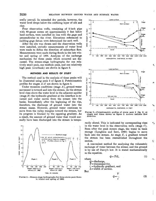
The stream-stage hydrographs for one relatively<br />
small peak, one medium peak, and one relatively<br />
high peak (overbank) are shown in figure 2.<br />
METHODS AND RESULTS ·OF STUDY<br />
The method used in the analysis of these peaks will<br />
be illustrated using peak 3 of figure 2. Potentiometric<br />
profiles for stages A -E are shown in figure 3.<br />
Under recession conditions (stage .A.), ground-water<br />
movement is toward and into the stream. As the stream<br />
level rises above the water level in the adjacent aquifer<br />
(stage B) the hydraulic gradient at the interface is reversed<br />
and water moves from the stream into the<br />
banks. Immediately after the beginning of the rise,<br />
therefore, the discharge of ground water into the<br />
stream ceases. However, ground water continues to<br />
move from the valley margins toward the stream, but<br />
its progress is blocked by the opposing gradient. As<br />
a result, the amount of ground water that would normally<br />
have been discharged into the stream is tempo-<br />
14<br />
13<br />
12<br />
t;j<br />
l.lJ 11<br />
L&..<br />
z<br />
~ 10<br />
:I:<br />
(!)<br />
ijj 9<br />
:I:<br />
w<br />
(!) 8<br />
<<br />
(!)<br />
6<br />
Peak 1<br />
----- Bankfull stage<br />
Time .at which potentiometric{A 8<br />
C<br />
0<br />
E<br />
prof1les were made for stages 1 1 1 1 1<br />
A-E. Profiles shown on figure<br />
3<br />
50 100 150 200 250 0 50 100 150 0 50 100 150<br />
Began 1800 hours<br />
January 27, 1968<br />
Began 1530 hours<br />
March 24, 1968<br />
Began 1700 hours<br />
April 3, 1968<br />
TIME, IN HOURS<br />
E'muRE 2.~Stream-stage hydrographs for three storm-peak flows<br />
in winter and .spring of 1968.<br />
WATER AND SURFACE WATER<br />
13 Land surface<br />
4 3<br />
12 Well number<br />
11<br />
l.lJ<br />
(!)<br />
<<br />
(!) 7<br />
6<br />
13<br />
12<br />
t;j 11<br />
l.lJ<br />
L&..<br />
~ 10<br />
~<br />
a 9<br />
ijj<br />
J:<br />
w 8<br />
(!)<br />
<<br />
(!) 7<br />
6<br />
0 100 200 300 400 500 600 700 800 900 1000 1100 1200<br />
HORIZONTAL DISTANCE, IN FEET<br />
Land surface<br />
I<br />
4 3 2 Gage<br />
Well number<br />
Silt and clay<br />
----------------~--~<br />
Sand<br />
'-<br />
0 100 200 300 400 500 600 700 800 900 1000 1100 1200<br />
HORIZONTAL DISTANCE, IN FEET<br />
FIGURE 3.-Potentiometric profiles of storm peak 3 (fig. 2) at<br />
stages and times shown on figure 2. Arrows indicate flow<br />
direction.<br />
rarily s'tored. This is indicated by corresponding rises<br />
in the water level in the observation wells (stage 0).<br />
Soon after the peak stream stage, the water in bank<br />
storage (Langbein and Iseri, 1960) begins to move<br />
back into the stream. At stage E, a gradient toward<br />
the stream has been reestablished throughout the<br />
section.<br />
A convenient method for analyzing the volumetric<br />
exchange of water between the stream and the ground<br />
is by use of Darcy's law. It is stated mathematically<br />
as the equation.<br />
Q=TiL,<br />
(1)<br />
where<br />
Q= dischar~e,<br />
T~ transmissivity,<br />
i =hydraulic gradient, and<br />
L==width of section. ·<br />
But<br />
v<br />
Q=-,<br />
(2)<br />
t<br />
., '<br />
""'<br />
·~!<br />
~' "·