SMS Siemag AG - Alu-web.de
SMS Siemag AG - Alu-web.de
SMS Siemag AG - Alu-web.de

Create successful ePaper yourself
Turn your PDF publications into a flip-book with our unique Google optimized e-Paper software.
SPe CIAL<br />
ALUMINIUM ROLLLINg INDUSTRY<br />
Recent operational experience with the<br />
Dynamic Shape Roll on aluminium cold mills<br />
P. J. Lawlor B.Tech, C. eng, FIMeche, section lea<strong>de</strong>r Process engineering – <strong>Alu</strong>minium, Siemens VAI<br />
Customer requirements are becoming<br />
ever more <strong>de</strong>manding in terms not only<br />
of product quality but also operational<br />
flexibility. The Dynamic Shape Roll<br />
(DSR) is the most capable mill actuator<br />
currently available to meet these challenges.<br />
Recent experience has clearly<br />
<strong>de</strong>monstrated the benefits of the DSR<br />
technology. Exceptional capability in<br />
terms of head end flatness and overall dynamic<br />
performance can be <strong>de</strong>monstrated.<br />
The ability to handle product width<br />
changes is unrivalled by any other actuator.<br />
The DSR can easily be operated and<br />
maintained by correctly trained operators<br />
and mill technicians.<br />
The DSR has its origins back in the paper industry<br />
with the Nipco roll from Sulzer Escher<br />
Wyss. Paper mills have always ten<strong>de</strong>d to be<br />
much wi<strong>de</strong>r than mills in the metals industry.<br />
This means that the length to diameter ratio of<br />
the rolls is large and thus a number of problems<br />
arise, such as roll stability, the bending<br />
effect being concentrated at the roll ends and<br />
so on. To overcome these issues the Nipco<br />
roll was <strong>de</strong>veloped to give improved control<br />
un<strong>de</strong>r these conditions. Siemens have taken<br />
this technology and exten<strong>de</strong>d it into the metals<br />
rolling field.<br />
DSR overview<br />
The DSR is a replacement for one of the backup<br />
rolls (usually the top one) and can be incorporated<br />
within the new mill or as a retrofit<br />
solution. It consists of a hollow shell rotating<br />
about static beam that has been mounted between<br />
two back-up chocks. An arrangement<br />
of hydraulic pads generate load on the insi<strong>de</strong><br />
face of the shell and this transfers through to<br />
the workroll to generate the rolling load. The<br />
clear advantage of this is that the load can be<br />
applied directly where it is required and not<br />
simply at the roll ends, as in either a conventional<br />
4-high or 6-high. This is illustrated in<br />
Fig. 1. This clearly enables the load distribution<br />
to be controlled more directly, thus helping<br />
flatness and threading.<br />
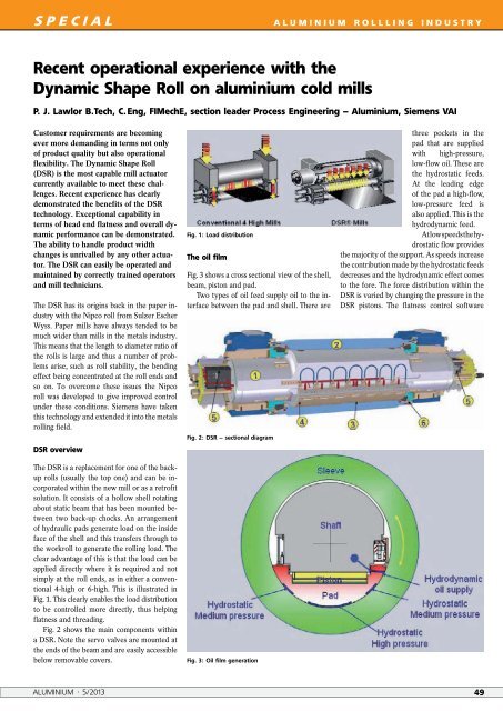
Fig. 2 shows the main components within<br />
a DSR. Note the servo valves are mounted at<br />
the ends of the beam and are easily accessible<br />
below removable covers.<br />
Fig. 1: Load distribution<br />
The oil film<br />
Fig. 3 shows a cross sectional view of the shell,<br />
beam, piston and pad.<br />
Two types of oil feed supply oil to the interface<br />
between the pad and shell. There are<br />
Fig. 2: DSR – sectional diagram<br />
Fig. 3: Oil film generation<br />
three pockets in the<br />
pad that are supplied<br />
with high-pressure,<br />
low-flow oil. These are<br />
the hydrostatic feeds.<br />
At the leading edge<br />
of the pad a high-flow,<br />
low-pressure feed is<br />
also applied. This is the<br />
hydrodynamic feed.<br />
At low speeds the hydrostatic<br />
flow provi<strong>de</strong>s<br />
the majority of the support. As speeds increase<br />
the contribution ma<strong>de</strong> by the hydrostatic feeds<br />
<strong>de</strong>creases and the hydrodynamic effect comes<br />
to the fore. The force distribution within the<br />
DSR is varied by changing the pressure in the<br />
DSR pistons. The flatness control software<br />
ALUMINIUM · 5/2013 49