Download Volume II Accomplisments (28 Mb pdf). - IRIS
Download Volume II Accomplisments (28 Mb pdf). - IRIS
Download Volume II Accomplisments (28 Mb pdf). - IRIS

Create successful ePaper yourself
Turn your PDF publications into a flip-book with our unique Google optimized e-Paper software.
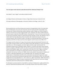
Adjoint Tomography of the Southern California Crust<br />
Carl Tape (Harvard University), Qinya Liu (University of Toronto), Alessia Maggi (University of Strasbourg), Jeroen<br />
Tromp (Princeton University)<br />
We iteratively improve a 3D tomographic model of the southern California crust using numerical simulations of seismicwave<br />
propagation based on a spectral-element method (SEM) in combination with an adjoint method. The initial 3D model is provided<br />
by the Southern California Earthquake Center. The data set comprises three-component seismicwaveforms (i.e. both body<br />
and surface waves), filtered over the period range 2-30 s, from 143 local earthquakes recorded by a network of 203 stations. Time<br />
windows for measurements are automatically selected by the FLEXWIN algorithm. The misfit function in the tomographic inversion<br />
is based on frequency-dependent multitaper traveltime differences. The gradient of the misfit function and related finitefrequency<br />
sensitivity kernels for each earthquake are computed using an adjoint technique. The kernels are combined using a<br />
source subspace projection method to compute a model update at each iteration of a gradient-based minimization algorithm. The<br />
inversion involved 16 iterations, which required 6800 wavefield simulations. The new crustal model, m16, is described in terms of<br />
independent shear (Vs) and bulk-sound (Vb) wave speed variations. It exhibits strong heterogeneity, including local changes of<br />
+/- 30 percent with respect to the initial 3D model. The model reveals several features that relate to geological observations, such<br />
as sedimentary basins, exhumed batholiths, and contrasting lithologies across faults. The quality of the new model is validated by<br />
quantifying waveform misfits of full-length seismograms from 91 earthquakes that were not used in the tomographic inversion.<br />
The new model provides more accurate synthetic seismograms that will benefit seismic hazard assessment.<br />
References<br />
Tape, C., Liu, Q., Maggi, A., Tromp, J., 2009, Adjoint tomography of the southern California crust, Science, 325, 988–992.<br />
Tape, C., Liu, Q., Maggi, A., Tromp, J., 2010, Seismic tomography of the southern California crust based on spectral-element and adjoint methods,<br />
Geophys. J. Int., 180, 433-462.<br />
Maggi, A., Tape, C., Chen, M., Chao, D., Tromp, J., 2009, An automated time-window selection algorithm for seismic tomography, Geophys.<br />
J. Int., 178, 257–<strong>28</strong>1.<br />
Acknowledgements: Seismic waveforms were provided by the data centers listed in Table 2 (<strong>IRIS</strong>, SCEDC, NCEDC). All earthquake simulations were<br />
performed on the CITerra Dell cluster at the Division of Geological & Planetary Sciences (GPS) of the California Institute of Technology. We<br />
acknowledge support by the National Science Foundation under grant EAR-0711177. This research was supported by the Southern California<br />
Earthquake Center. SCEC is funded by NSF Cooperative Agreement EAR-0106924 and USGS Cooperative Agreement 02HQAG0008.<br />
Iterative improvement of a three-component seismogram.<br />
(A) Cross section of the Vs tomographic<br />
models for a path from a Mw 4.5 earthquake (star)<br />
on the White Wolf fault to station DAN (triangle) in<br />
the eastern Mojave Desert. Upper right is the initial<br />
3D model, m00; lower right is the final 3D model,<br />
m16; and lower left is the difference between the<br />
two, ln(m16/m00). Faults labeled for reference are<br />
San Andreas (SA), Garlock (G), and Camp Rock (CR).<br />
(B) Iterative three-component seismogram fits to<br />
data for models m00, m01, m04, and m16. Also<br />
shown are synthetic seismograms computed for a<br />
standard 1D model. Synthetic seismograms (red)<br />
and recorded seismograms (black), filtered over<br />
the period range 6 to 30 s. Left column, vertical<br />
component (Z); center column, radial component<br />
(R); right column, transverse component (T). Inset<br />
“DT” label indicates the time shift between the<br />
two windowed records that provides the maximum<br />
cross-correlation.<br />
2010 <strong>IRIS</strong> Core Programs Proposal | <strong>Volume</strong> <strong>II</strong> | Crustal Structure | <strong>II</strong>-115