Download Volume II Accomplisments (28 Mb pdf). - IRIS
Download Volume II Accomplisments (28 Mb pdf). - IRIS
Download Volume II Accomplisments (28 Mb pdf). - IRIS

Create successful ePaper yourself
Turn your PDF publications into a flip-book with our unique Google optimized e-Paper software.
40<br />
Crustal Structure beneath the High Lava Plains of Eastern Oregon<br />
and Surrounding Regions from Receiver Function Analysis<br />
Kevin C. Eagar and Matthew J. Fouch (Arizona State University), David E. James and Richard W. Carlson (Carnegie<br />
Institution of Washington)<br />
We analyze teleseismic P-to-S receiver functions to image crustal structure beneath the High Lava Plains (HLP) of eastern<br />
Oregon and surrounding regions. The coverage from 206 broadband seismic stations provides the first opportunity to resolve<br />
small scale variations in crustal composition, thickness, and heterogeneity. We utilize both Hκ stacking and a new Gaussianweighted<br />
common conversion point stacking technique. We find crust that is ≥ 40 km thick beneath the Cascades, Idaho Batholith,<br />
and Owyhee Plateau, and thinner (~31 km) crust beneath the HLP and northern Great Basin. Low Poisson’s ratios of ~0.250 characterize<br />
the granitic Idaho Batholith, while the Owyhee Plateau possesses values of ~0.270, typical of average continental crust.<br />
The Owyhee Plateau is a thick simple crustal block with distinct edges at depth. The western HLP exhibits high average values of<br />
0.295, expected from widespread basaltic volcanism. Combined with other geological and geophysical observations, the areas of<br />
high Poisson’s ratios (~0.320) and low velocity zones in the crust beneath north-central and southern Oregon are consistent with<br />
the presence of partial melt on either side of the HLP track, suggesting a central zone where crustal melts have drained to the surface,<br />
perhaps enabled by the Brothers Fault zone. Thicker crust and an anomalous N-S band of low Poisson’s ratios (~0.252) skirting<br />
the Steens Mountain escarpment is consistent with residuum from a mid-crustal magma source of the massive flood basalts,<br />
supporting the view of extensive mafic under- and intraplating of the crust from Cenozoic volcanism.<br />
References<br />
Eagar, K.C., M.J. Fouch, D.E. James, R.W. Carlson, 46˚N and the High C Lava Plains Seismic Working Group, Crustal structure beneath the High Lava<br />
Plains of Eastern Oregon and surrounding regions from receiver function analysis, submitted to J. Geophys. Res., June 2010.<br />
45˚N<br />
B<br />
Acknowledgements: This work would not have been possible without high quality seismic data provided through the hard work of the TA and the HLP<br />
44˚N<br />
Seismic Experiment teams (http://www.dtm.ciw.edu/research/HLP), A<br />
and the services A’ of the <strong>IRIS</strong> DMC. As always, the <strong>IRIS</strong> PASSCAL program<br />
provided world-class technical field support. 43˚N A special thanks goes to Jenda Johnson, whose contributions to the project have been innumerable<br />
and immeasurable, and Steven Golden for providing field and data support. We would also like to acknowledge the work and productive discussions<br />
on the crustal evolution with the other PIs of the HLP project, including Anita Grunder, Bill Hart, Tim Grove, Randy Keller, Steve Harder,<br />
42˚N<br />
B’<br />
and Bob Duncan. This research was supported 41˚N by National Science Foundation awards EAR-0548<strong>28</strong>8 (MJF EarthScope CAREER grant), EAR-<br />
C’<br />
0507248 (MJF Continental Dynamics High Lava Plains grant) and EAR-0506914 (DEJ/RWC Continental Dynamics High Lava Plains grant).<br />
44˚N<br />
a)<br />
45˚N 42˚N<br />
43˚N 40˚N<br />
Depth (km)<br />
Depth (km)<br />
46˚N<br />
46˚N<br />
44˚N<br />
41˚N<br />
A<br />
0<br />
3<br />
0<br />
10<br />
20<br />
30<br />
40<br />
50<br />
60<br />
70<br />
80<br />
B<br />
0<br />
3<br />
0<br />
10<br />
20<br />
30<br />
40<br />
50<br />
122˚W 120˚W 118˚W 116˚W 114˚W<br />
CM<br />
HLP C<br />
SRP<br />
B<br />
A<br />
25 30 35 40 45<br />
Moho Depth (km)<br />
42˚N<br />
b)<br />
c)<br />
50<br />
122˚W 120˚W 118˚W 116˚W 114˚W<br />
45<br />
50<br />
35<br />
100<br />
CM<br />
LVZ?<br />
CM<br />
35<br />
30<br />
MP<br />
35<br />
30<br />
200<br />
CRB<br />
35<br />
41 35<br />
B’<br />
100<br />
200<br />
300<br />
400<br />
500<br />
600<br />
700<br />
800<br />
HLP<br />
LVZ?<br />
0.704 line<br />
C’<br />
Distance (km)<br />
300<br />
30<br />
BM<br />
30<br />
BM<br />
35<br />
30<br />
400<br />
30<br />
0.704 line<br />
OP<br />
0.706 line<br />
0.706 line<br />
GB<br />
500<br />
30<br />
35<br />
OP<br />
40<br />
35<br />
IB<br />
35<br />
.704<br />
.706<br />
600<br />
A’<br />
IB<br />
B’<br />
40<br />
35<br />
GB<br />
2010 <strong>IRIS</strong> Core Programs Proposal | <strong>Volume</strong> <strong>II</strong> | Crustal Structure | <strong>II</strong>-125<br />
35.5<br />
A’<br />
700<br />
a)<br />
b)<br />
3<br />
46˚N 0<br />
10<br />
20<br />
30<br />
40<br />
50<br />
44˚N 60<br />
70<br />
80<br />
Depth (km)<br />
c)<br />
42˚N<br />
3<br />
0<br />
10<br />
40˚N<br />
20<br />
30<br />
40<br />
50<br />
60<br />
70<br />
80<br />
Depth (km)<br />
d)<br />
Depth (km)<br />
0<br />
0<br />
C<br />
0<br />
122˚W 120˚W 118˚W 116˚W 114˚W<br />
A<br />
Distance (km)<br />
A’<br />
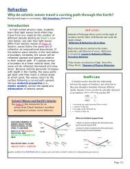
Figure 1: Map of Moho depth derived from H-k<br />
stacking<br />
CM<br />
analysis.<br />
BM<br />
Single station results<br />
IB<br />
(colored<br />
circles) are smoothed over a 10 x 10 km<br />
grid using splines under tension with a tension<br />
LVZ?<br />
factor of 0.3 using the Generic Mapping Tools<br />
30<br />
[Smith<br />
41<br />
and Wessel, 35 1990]. Red colors<br />
40<br />
denote<br />
shallower Moho; blue colors denote deeper<br />
Moho; gray regions represent areas of limited<br />
sampling in this study. Black solid lines denote<br />
5 km contours. 87Sr/86Sr isopleths of 0.704<br />
Band 0.706 (“.704” and “.706” lines) denoted B’ by<br />
black dashed lines. Geologic provinces include<br />
Cascade<br />
CM<br />
volcanic<br />
HLP<br />
arc (CM), Blue<br />
OPMountains GB<br />
(BM),<br />
High Lava Plains (HLP), Columbia River basin<br />
(CRB), Snake<br />
LVZ?<br />
River Plain (SRP), Idaho batholith<br />
(IB), Owyhee Plateau (OP), Modoc Plateau (MP),<br />
and Great Basin (GB).<br />
100<br />
41.5 37.5 35.5<br />
100<br />
200<br />
100<br />
200<br />
300<br />
400<br />
500<br />
600<br />
700<br />
800<br />
200<br />
300<br />
300<br />
400<br />
-0.20<br />
-0.15-0.10-0.050.000.050.100.150.20<br />
Amplitude<br />
42<br />
400<br />
3<br />
0<br />
10<br />
CRB BM HLP<br />
20<br />
LVZ?<br />
30<br />
40<br />
80<br />
50<br />
60<br />
37 34.5<br />
70<br />
37<br />
33<br />
.704<br />
500<br />
.704<br />
.706<br />
600<br />
43.5 35.5<br />
500<br />
.706<br />
GB<br />
31.5<br />
700<br />
C’<br />
600<br />
46˚N<br />
44˚N<br />
42˚N<br />
40˚N<br />
CM<br />
.250<br />
.275<br />
122˚W 120˚W 118˚W 116˚W 114˚W<br />
.300<br />
.325<br />
.300<br />
.300 .300<br />
HLP<br />
.325<br />
.300<br />
MP<br />
.275<br />
CRB<br />
.275<br />
.275<br />
0.704 line<br />
0.25<br />
BM<br />
.250<br />
.275<br />
0.205 0.240 0.275 0.310 0.345<br />
Poisson’s Ratio<br />
.275<br />
0.704 line<br />
OP<br />
0.706 line<br />
.250<br />
.225<br />
0.<br />
.250<br />
.300<br />
0.706 line<br />
.300<br />
GB<br />
.275<br />
IB<br />
.250<br />
.225<br />
.250<br />
.275<br />
SRP<br />
46˚N<br />
44˚N<br />
42˚N<br />
40˚N<br />
Figure 3: Map of Poisson’s ratios derived from H-k<br />
stacking analysis. Smoothing parameters and geological/geochemical<br />
features are the same as in<br />
figure 1. Black solid lines denote 0.025 contours.<br />
Figure 2: Cross-sections of Moho depths and crustal features.<br />
Geologic and geochemical provinces labeled as in the maps.<br />
Colored background is amplitudes from GCCP stacking. Solid line<br />
with depth labels is Moho valued picked from maximum amplitudes<br />
in GCCP stacks. Dotted black lines labeled LVZ are areas of<br />
strong negative amplitudes in the crust. White stars represent Hk<br />
Moho depths from the nearest stations along each profile. Profile<br />
A-A’ is oriented east-west; profile C-C’ is oriented north-south.