- Page 1 and 2:
FS-1030D SERVICE MANUAL Published i
- Page 3 and 4:
Safety precautions This booklet pro
- Page 5 and 6:
1. Installation Precautions WARNING
- Page 7 and 8:
Do not pull on the AC power cord or
- Page 9 and 10:
CONTENTS 2G6 1-1 Specifications 1-1
- Page 11 and 12:
(1-1) Process unit mechanism ......
- Page 13 and 14:
2G6-1 1-1-1 Specifications Type ...
- Page 15 and 16:
2G6 1-1-2 Name of parts (1) Overall
- Page 17 and 18:
2G6 1-1-3 Machine cross section Pr
- Page 19 and 20:
2G6 1-2-1 Process unit (drum) Note
- Page 21 and 22:
2G6 1-3-1 Unpacking and installatio
- Page 23 and 24:
2G6 Remove the tape and protective
- Page 25 and 26:
2G6 5. Set the toner container into
- Page 27 and 28:
2G6 Load paper. 1. Pull the cassett
- Page 29 and 30:
2G6 1-3-2 Installing the expanding
- Page 31 and 32:
2G6 1-3-4 Installing the network in
- Page 33 and 34:
2G6 1-4-1 Maintenance The product i
- Page 35 and 36:
2G6 Service items Description Detai
- Page 37 and 38:
2G6 Service items Printing an event
- Page 39 and 40:
2G6 Service items Description Item
- Page 41 and 42:
2G6 Service items Description Items
- Page 43 and 44:
2G6 1-5-1 Paper misfeed detection (
- Page 45 and 46:
2G6 Code Error indications Contents
- Page 47 and 48:
2G6 Check procedures/corrective mea
- Page 49 and 50:
2G6 Check procedures/corrective mea
- Page 51 and 52:
2G6 Code Error indications Contents
- Page 53 and 54:
2G6 Code Error indications Contents
- Page 55 and 56:
2G6 (1) No image appears (entirely
- Page 57 and 58:
2G6 (6) A black line appears longit
- Page 59 and 60:
2G6 (12)Offset occurs. Causes 1. De
- Page 61 and 62:
2G6 Problem Causes Check procedures
- Page 63 and 64:
2G6 1-5-5 Mechanical problems Probl
- Page 65 and 66:
2G6 1-6-1 Precautions for assembly
- Page 67 and 68:
2G6 1-6-3 Removing the principal ou
- Page 69 and 70:
2G6 1-6-4 Removing the feed roller
- Page 71 and 72: 2G6 6. Remove one screw. 7. Remove
- Page 73 and 74: 2G6 1-6-7 Removing the principal PW
- Page 75 and 76: 2G6 6. Remove two screws at the bac
- Page 77 and 78: 2G6 (4) Removing the bias PWB 1. Re
- Page 79 and 80: 2G6 1-6-8 Removing the main motor a
- Page 81 and 82: 2G6 10. Remove the main PWB (See pa
- Page 83 and 84: 2G6 1-6-9 Removing and splitting th
- Page 85 and 86: 2G6 (1) Removing the separation cla
- Page 87 and 88: 2G6 (3) Removing the heat roller WA
- Page 89 and 90: 2G6 (4) Removing the fuser thermist
- Page 91 and 92: 2G6 (6) Removing the press roller W
- Page 93 and 94: 2G6 4. Remove three screws. 5. Remo
- Page 95 and 96: 2G6 1-6-11 Removing the main charge
- Page 97 and 98: 2G6 1-7-1 Upgrading the firmware on
- Page 99 and 100: 2G6 (3) Downloading the firmware fr
- Page 101 and 102: 2G6 2-1-1 Paper feeding system The
- Page 103 and 104: 2G6 (2) Paper feeding mechanism
- Page 105 and 106: 2G6 Upper exit roller forward/rever
- Page 107 and 108: 2G6 (1-1) Process unit mechanism
- Page 109 and 110: 2G6 (2-2) Charging the drum The fol
- Page 111 and 112: 2G6 (3-1) Laser scanner unit
- Page 113 and 114: (4) Development The latent image co
- Page 115 and 116: (6) Fusing The toner on the paper i
- Page 117 and 118: (7) Cleaning After the transferring
- Page 119 and 120: 2G6 2-2-1 Electrical parts layout (
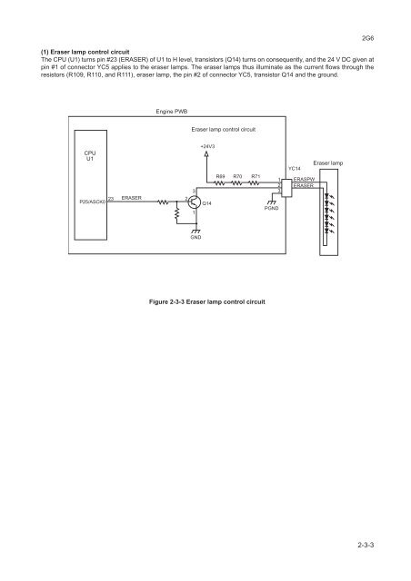
- Page 121: 2G6 2-3-1 Main PWB Xtal(System) CXI
- Page 125 and 126: (3) Polygon motor control circuit T
- Page 127 and 128: 2G6 Connector Pin No. Signal I/O Vo
- Page 129 and 130: 2G6 Connector Pin No. Signal I/O Vo
- Page 131 and 132: 2G6 2-3-5 High voltage unit The Hig
- Page 133 and 134: 2G6 Timing chart No. 1 Paper casset
- Page 135 and 136: 2G6-2 2-4-3 Wiring diagram +24V3 PG
- Page 137 and 138: MEMO: