FS-1030D Service Manual - kyocera
FS-1030D Service Manual - kyocera
FS-1030D Service Manual - kyocera

You also want an ePaper? Increase the reach of your titles
YUMPU automatically turns print PDFs into web optimized ePapers that Google loves.
2G6<br />
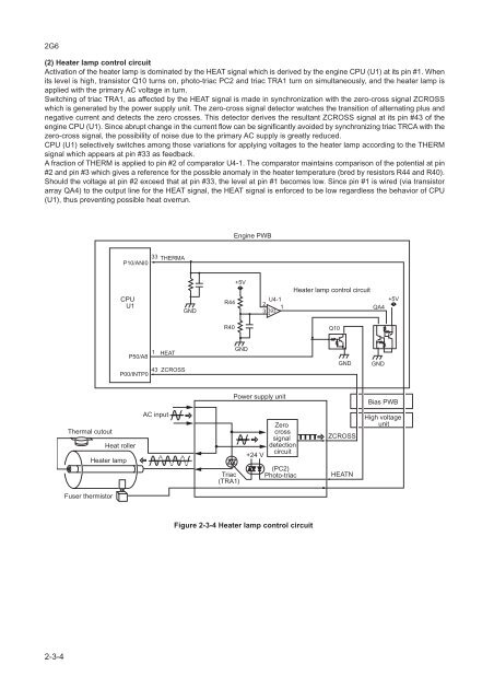
(2) Heater lamp control circuit<br />
Activation of the heater lamp is dominated by the HEAT signal which is derived by the engine CPU (U1) at its pin #1. When<br />
its level is high, transistor Q10 turns on, photo-triac PC2 and triac TRA1 turn on simultaneously, and the heater lamp is<br />
applied with the primary AC voltage in turn.<br />
Switching of triac TRA1, as affected by the HEAT signal is made in synchronization with the zero-cross signal ZCROSS<br />
which is generated by the power supply unit. The zero-cross signal detector watches the transition of alternating plus and<br />
negative current and detects the zero crosses. This detector derives the resultant ZCROSS signal at its pin #43 of the<br />
engine CPU (U1). Since abrupt change in the current flow can be significantly avoided by synchronizing triac TRCA with the<br />
zero-cross signal, the possibility of noise due to the primary AC supply is greatly reduced.<br />
CPU (U1) selectively switches among those variations for applying voltages to the heater lamp according to the THERM<br />
signal which appears at pin #33 as feedback.<br />
A fraction of THERM is applied to pin #2 of comparator U4-1. The comparator maintains comparison of the potential at pin<br />
#2 and pin #3 which gives a reference for the possible anomaly in the heater temperature (bred by resistors R44 and R40).<br />
Should the voltage at pin #2 exceed that at pin #33, the level at pin #1 becomes low. Since pin #1 is wired (via transistor<br />
array QA4) to the output line for the HEAT signal, the HEAT signal is enforced to be low regardless the behavior of CPU<br />
(U1), thus preventing possible heat overrun.<br />
Engine PWB<br />
33 THERMA<br />
P10/ANI0<br />
CPU<br />
U1<br />
GND<br />
R44<br />
+5V<br />
U4-1<br />
2<br />
- 1<br />
3 393<br />
+<br />
Heater lamp control circuit<br />
QA4<br />
+5V<br />
R40<br />
Q10<br />
1 HEAT<br />
P50/A8<br />
43 ZCROSS<br />
P00/INTP0<br />
GND<br />
GND<br />
GND<br />
Power supply unit<br />
Bias PWB<br />
Thermal cutout<br />
Heat roller<br />
Heater lamp<br />
AC input<br />
Triac<br />
(TRA1)<br />
+24 V<br />
Zero<br />
cross<br />
signal<br />
detection<br />
circuit<br />
(PC2)<br />
Photo-triac<br />
ZCROSS<br />
HEATN<br />
High voltage<br />
unit<br />
Fuser thermistor<br />
Figure 2-3-4 Heater lamp control circuit<br />
2-3-4