FS-1030D Service Manual - kyocera
FS-1030D Service Manual - kyocera
FS-1030D Service Manual - kyocera

You also want an ePaper? Increase the reach of your titles
YUMPU automatically turns print PDFs into web optimized ePapers that Google loves.
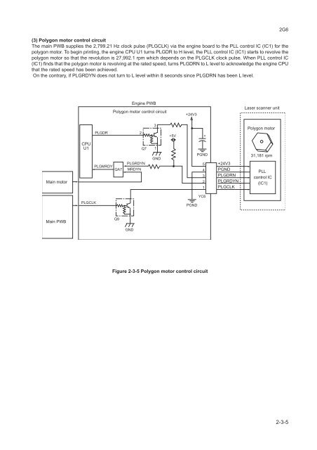
(3) Polygon motor control circuit<br />
The main PWB supplies the 2,799.21 Hz clock pulse (PLGCLK) via the engine board to the PLL control IC (IC1) for the<br />
polygon motor. To begin printing, the engine CPU U1 turns PLGDR to H level, the PLL control IC (IC1) starts to revolve the<br />
polygon motor so that the revolution is 27,992.1 rpm which depends on the PLGCLK clock pulse. When PLL control IC<br />
(IC1) finds that the polygon motor is revolving at the rated speed, turns PLGDRN to L level to acknowledge the engine CPU<br />
that the rated speed has been achieved.<br />
On the contrary, if PLGRDYN does not turn to L level within 8 seconds since PLGDRN has been L level.<br />
2G6<br />
Engine PWB<br />
Polygon motor control circuit<br />
+24V3<br />
Laser scanner unit<br />
PLGDR<br />
2<br />
3<br />
+5V +<br />
Polygon motor<br />
Main motor<br />
CPU<br />
U1<br />
PLGMRDY<br />
QA7<br />
Q7<br />
PLGRDYN<br />
MRDYN<br />
1<br />
GND<br />
PGND<br />
5<br />
4<br />
3<br />
2<br />
1<br />
+24V3<br />
PGND<br />
PLGDRN<br />
PLGRDYN<br />
PLGCLK<br />
31,181 rpm<br />
PLL<br />
control IC<br />
(IC1)<br />
PLGCLK<br />
PGND<br />
YC6<br />
Main PWB<br />
Q9<br />
GND<br />
Figure 2-3-5 Polygon motor control circuit<br />
2-3-5