Intel Server Board S1200BT - PROconsult Data A/S
Intel Server Board S1200BT - PROconsult Data A/S
Intel Server Board S1200BT - PROconsult Data A/S

Create successful ePaper yourself
Turn your PDF publications into a flip-book with our unique Google optimized e-Paper software.
Connector/Header Locations and Pin-outs<br />
<strong>Intel</strong>® <strong>Server</strong> <strong>Board</strong> <strong>S1200BT</strong> TPS<br />
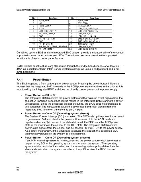
Pin Signal Name Pin Signal Name<br />
1 P3V3_AUX 2 P3V3_AUX<br />
3 NC 4 P5V_STBY<br />
5 PWR_LED_N 6 TP_LED_ID_N<br />
7 P3V3 8 LED_STS_GREEN_N<br />
9 LED_HDD_ACT_N 10 LED_STS_AMBER_N<br />
11 FP_PWR_BTN_N 12 LED_ NIC1_ACT<br />
13 GND 14 LED_NIC1_LINK_N<br />
15 FP_RST_BTN_N 16 SMB_SEN_3V3SB_DAT<br />
17 GND 18 SMB_SEN_3V3SB_CLK<br />
19 FP_ID_BTN_N 20 INTRUDER_HDR<br />
21 PU_FM_SIO_TEMP_SENSOR 22 LED_ NIC2_ACT<br />
23 FP_NMI_BTN_N 24 LED_ NIC2_LINK_N<br />
Combined system BIOS and the Integrated BMC support provide the functionality of the various<br />
supported control panel buttons and LEDs. The following sections describe the supported<br />
functionality of each control panel feature.<br />
Note: Control panel features are also routed through the bridge board connector at location<br />
J1C1 as is implemented in <strong>Intel</strong> ® <strong>Server</strong> Systems configured using a bridge board and a hotswap<br />
backplane.<br />
7.4.1 Power Button<br />
The BIOS supports a front control panel power button. Pressing the power button initiates a<br />
request that the Integrated BMC forwards to the ACPI power state machines in the chipset. It is<br />
monitored by the Integrated BMC and does not directly control power on the power supply.<br />
• Power Button — Off to On<br />
The Integrated BMC monitors the power button and the wake-up event signals from the<br />
chipset. A transition from either source results in the Integrated BMC starting the powerup<br />
sequence. Since the processor are not executing, the BIOS does not participate in<br />
this sequence. The hardware receives the power good and reset signals from the<br />
Integrated BMC and then transitions to an ON state.<br />
• Power Button — On to Off (Operating system absent)<br />
The System Control Interrupt (SCI) is masked. The BIOS sets up the power button event<br />
to generate an SMI and checks the power button status bit in the ACPI hardware<br />
registers when an SMI occurs. If the status bit is set, the BIOS sets the ACPI power<br />
state of the machine in the chipset to the OFF state. The Integrated BMC monitors<br />
power state signals from the chipset and de-asserts PS_PWR_ON to the power supply.<br />
As a safety mechanism, if the BIOS fails to service the request, the Integrated BMC<br />
automatically powers off the system in 4 to 5 seconds.<br />
• Power Button — On to Off (Operating system present)<br />
If an ACPI operating system is running, pressing the power button switch generates a<br />
request using SCI to the operating system to shut down the system. The operating<br />
system retains control of the system and the operating system policy determines the<br />
sleep state into which the system transitions, if any. Otherwise, the BIOS turns off<br />
the system.<br />
94<br />
<strong>Intel</strong> order number G13326-003<br />
Revision 1.0