Intel Server Board S1200BT - PROconsult Data A/S
Intel Server Board S1200BT - PROconsult Data A/S
Intel Server Board S1200BT - PROconsult Data A/S

Create successful ePaper yourself
Turn your PDF publications into a flip-book with our unique Google optimized e-Paper software.
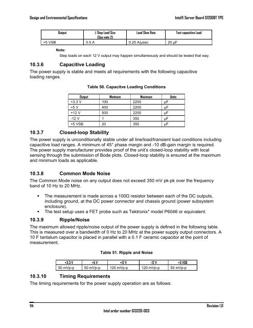
Design and Environmental Specifications<br />
<strong>Intel</strong>® <strong>Server</strong> <strong>Board</strong> <strong>S1200BT</strong> TPS<br />
Output<br />
∆ Step Load Size<br />
Load Slew Rate<br />
Test capacitive Load<br />
(See note 2)<br />
+5 VSB 0.5 A 0.25 A/µsec 20 µF<br />
Note:<br />
Step loads on each 12 V output may happen simultaneously and should be tested that way.<br />
10.3.6 Capacitive Loading<br />
The power supply is stable and meets all requirements with the following capacitive<br />
loading ranges.<br />
10.3.7 Closed-loop Stability<br />
Table 50. Capacitve Loading Conditions<br />
Output Minimum Maximum Units<br />
+3.3 V 100 2200 µF<br />
+5 V 400 2200 µF<br />
+12 V 500 2200 µF<br />
-12 V 1 350 µF<br />
+5 VSB 20 350 µF<br />
The power supply is unconditionally stable under all line/load/transient load conditions including<br />
capacitive load ranges. A minimum of 45°phase margin and -10 dB-gain margin is required.<br />
The power supply manufacturer provides proof of the unit‘s closed-loop stability with local<br />
sensing through the submission of Bode plots. Closed-loop stability is ensured at the maximum<br />
and minimum loads as applicable.<br />
10.3.8 Common Mode Noise<br />
The Common Mode noise on any output does not exceed 350 mV pk-pk over the frequency<br />
band of 10 Hz to 20 MHz.<br />
• The measurement is made across a 100Ω resistor between each of the DC outputs,<br />
including ground, at the DC power connector and chassis ground (power subsystem<br />
enclosure).<br />
• The test setup uses a FET probe such as Tektronix* model P6046 or equivalent.<br />
10.3.9 Ripple/Noise<br />
The maximum allowed ripple/noise output of the power supply is defined in the following table.<br />
This is measured over a bandwidth of 0 Hz to 20 MHz at the power supply output connectors. A<br />
10 F tantalum capacitor is placed in parallel with a 0.1 F ceramic capacitor at the point of<br />
measurement.<br />
Table 51. Ripple and Noise<br />
+3.3 V +5 V +12 V -12 V +5 VSB<br />
50 mVp-p 50 mVp-p 120 mVp-p 120 mVp-p 50 mVp-p<br />
10.3.10 Timing Requirements<br />
The timing requirements for the power supply operation are as follows:<br />
114<br />
<strong>Intel</strong> order number G13326-003<br />
Revision 1.0