Intel Server Board S1200BT - PROconsult Data A/S
Intel Server Board S1200BT - PROconsult Data A/S
Intel Server Board S1200BT - PROconsult Data A/S

You also want an ePaper? Increase the reach of your titles
YUMPU automatically turns print PDFs into web optimized ePapers that Google loves.
<strong>Intel</strong>® <strong>Server</strong> <strong>Board</strong> <strong>S1200BT</strong> TPS<br />
Functional Architecture<br />
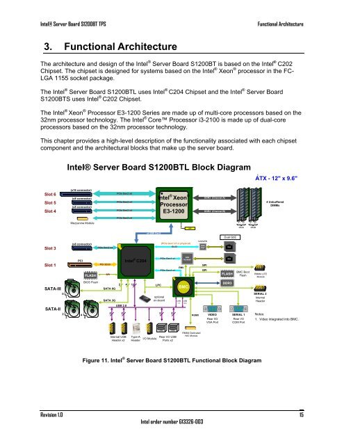
3. Functional Architecture<br />
The architecture and design of the <strong>Intel</strong> ® <strong>Server</strong> <strong>Board</strong> <strong>S1200BT</strong> is based on the <strong>Intel</strong> ® C202<br />
Chipset. The chipset is designed for systems based on the <strong>Intel</strong> ® Xeon ® processor in the FC-<br />
LGA 1155 socket package.<br />
The <strong>Intel</strong> ® <strong>Server</strong> <strong>Board</strong> <strong>S1200BT</strong>L uses <strong>Intel</strong> ® C204 Chipset and the <strong>Intel</strong> ® <strong>Server</strong> <strong>Board</strong><br />
<strong>S1200BT</strong>S uses <strong>Intel</strong> ® C202 Chipset.<br />
The <strong>Intel</strong> ® Xeon ® Processor E3-1200 Series are made up of multi-core processors based on the<br />
32nm processor technology. The <strong>Intel</strong> ® Core Processor i3-2100 is made up of dual-core<br />
processors based on the 32nm processor technology.<br />
This chapter provides a high-level description of the functionality associated with each chipset<br />
component and the architectural blocks that make up the server board.<br />
<strong>Intel</strong>® <strong>Server</strong> <strong>Board</strong> <strong>S1200BT</strong>L Block Diagram<br />
ATX - 12" x 9.6"<br />
Slot 6<br />
Slot 5<br />
Slot 4<br />
(x16 connector)<br />
(x8 connector)<br />
(x8 connector)<br />
PCIe Gen2 x8<br />
PCIe Gen2 x4<br />
PCIe Gen2 x4<br />
<strong>Intel</strong> ® Xeon ®<br />
Knoxvill<br />
Processor<br />
Socket H2<br />
E3-1200<br />
DDR3 (Channel A)<br />
DDR3 (Channel B)<br />
4 Unbuffered<br />
DIMMs<br />
PCIe Gen2 x4<br />
Mezzanine Module<br />
A1 A0 B1 B0<br />
XDP<br />
Ch A<br />
Ch B<br />
x4 DMI Gen2<br />
Dual GbE<br />
Slot 3<br />
(x8 connector)<br />
PCIe Gen2 x4<br />
(PCIe Gen1 x1 in physical)<br />
GLCI<br />
Lewisville<br />
GbE<br />
PHY<br />
GbE<br />
Slot 1<br />
PCI<br />
FLASH<br />
PCI 32/33<br />
SPI<br />
<strong>Intel</strong> ® C204<br />
PCIe Gen1 x1<br />
PCIe Gen1 x1<br />
RMII<br />
GbE<br />
Hartwell<br />
SPI<br />
SPI<br />
GbE<br />
FLASH<br />
BMC Boot<br />
Flash<br />
RMM4 LITE<br />
Module<br />
SATA-III<br />
SATA-II<br />
0<br />
1<br />
2<br />
3<br />
4<br />
5<br />
BIOS Flash<br />
SATA 6G<br />
SATA 3G<br />
2<br />
2<br />
USB 2.0<br />
2<br />
4 12<br />
TPM<br />
LPC<br />
optional<br />
on-board<br />
2<br />
2<br />
BMC Zoar<br />
USB<br />
1.1<br />
USB<br />
2.0<br />
RGMII<br />
VIDEO<br />
Rear I/O<br />
VGA Port<br />
DDR3<br />
SERIAL 1<br />
Rear I/O<br />
COM Port<br />
SERIAL 2<br />
Internal<br />
Header<br />
Notes:<br />
1. Video integrated into BMC.<br />
Internal USB<br />
Header x2<br />
Type-A<br />
Header<br />
I/O Module<br />
USB<br />
USB<br />
Rear I/O USB<br />
Ports x2<br />
RMM4 Dedicated<br />
NIC Module<br />
Figure 11. <strong>Intel</strong> ® <strong>Server</strong> <strong>Board</strong> <strong>S1200BT</strong>L Functional Block Diagram<br />
Revision 1.0<br />
<strong>Intel</strong> order number G13326-003<br />
15