Intel Server Board S1200BT - PROconsult Data A/S
Intel Server Board S1200BT - PROconsult Data A/S
Intel Server Board S1200BT - PROconsult Data A/S

Create successful ePaper yourself
Turn your PDF publications into a flip-book with our unique Google optimized e-Paper software.
Connector/Header Locations and Pin-outs<br />
<strong>Intel</strong>® <strong>Server</strong> <strong>Board</strong> <strong>S1200BT</strong> TPS<br />
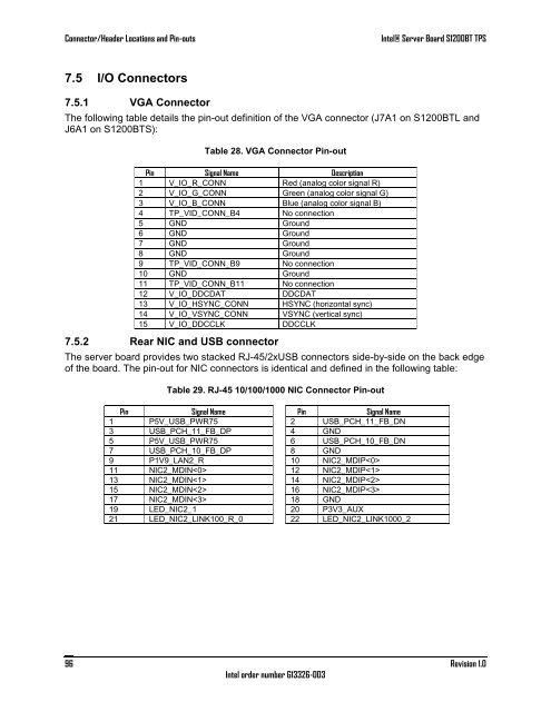
7.5 I/O Connectors<br />
7.5.1 VGA Connector<br />
The following table details the pin-out definition of the VGA connector (J7A1 on <strong>S1200BT</strong>L and<br />
J6A1 on <strong>S1200BT</strong>S):<br />
Table 28. VGA Connector Pin-out<br />
Pin Signal Name Description<br />
1 V_IO_R_CONN Red (analog color signal R)<br />
2 V_IO_G_CONN Green (analog color signal G)<br />
3 V_IO_B_CONN Blue (analog color signal B)<br />
4 TP_VID_CONN_B4 No connection<br />
5 GND Ground<br />
6 GND Ground<br />
7 GND Ground<br />
8 GND Ground<br />
9 TP_VID_CONN_B9 No connection<br />
10 GND Ground<br />
11 TP_VID_CONN_B11 No connection<br />
12 V_IO_DDCDAT DDCDAT<br />
13 V_IO_HSYNC_CONN HSYNC (horizontal sync)<br />
14 V_IO_VSYNC_CONN VSYNC (vertical sync)<br />
15 V_IO_DDCCLK DDCCLK<br />
7.5.2 Rear NIC and USB connector<br />
The server board provides two stacked RJ-45/2xUSB connectors side-by-side on the back edge<br />
of the board. The pin-out for NIC connectors is identical and defined in the following table:<br />
Table 29. RJ-45 10/100/1000 NIC Connector Pin-out<br />
Pin Signal Name Pin Signal Name<br />
1 P5V_USB_PWR75 2 USB_PCH_11_FB_DN<br />
3 USB_PCH_11_FB_DP 4 GND<br />
5 P5V_USB_PWR75 6 USB_PCH_10_FB_DN<br />
7 USB_PCH_10_FB_DP 8 GND<br />
9 P1V9_LAN2_R 10 NIC2_MDIP<br />
11 NIC2_MDIN 12 NIC2_MDIP<br />
13 NIC2_MDIN 14 NIC2_MDIP<br />
15 NIC2_MDIN 16 NIC2_MDIP<br />
17 NIC2_MDIN 18 GND<br />
19 LED_NIC2_1 20 P3V3_AUX<br />
21 LED_NIC2_LINK100_R_0 22 LED_NIC2_LINK1000_2<br />
96<br />
<strong>Intel</strong> order number G13326-003<br />
Revision 1.0