Intel Server Board S1200BT - PROconsult Data A/S
Intel Server Board S1200BT - PROconsult Data A/S
Intel Server Board S1200BT - PROconsult Data A/S

You also want an ePaper? Increase the reach of your titles
YUMPU automatically turns print PDFs into web optimized ePapers that Google loves.
<strong>Intel</strong>® <strong>Server</strong> <strong>Board</strong> <strong>S1200BT</strong> TPS<br />
Appendix C: POST Code Diagnostic LED Decoder<br />
Appendix C: POST Code Diagnostic LED Decoder<br />
During the system boot process, the BIOS executes a number of platform configuration<br />
processes, each of which is assigned a specific hex POST code number. As each configuration<br />
routine is started, the BIOS displays the POST code to the POST Code Diagnostic LEDs on the<br />
back edge of the server board. To assist in troubleshooting a system hang during the POST<br />
process, you can use the diagnostic LEDs to identify the last POST process executed.<br />
Later in POST, the BIOS displays POST Error Codes on the video monitor in the Error Manager<br />
display. Any POST Error Codes are automatically logged in the event log.<br />
The Diagnostic LEDs are a set of LEDs found on the back edge of the server board. The exact<br />
implementation may differ for some boards, but in general there are 8 Diagnostic LEDs which<br />
form a 2 hex digit (8 bit) code read left-to-right as facing the rear of the server.<br />
An LED which is ON represents a 1 bit value, and an LED which is OFF represents a 0 bit value.<br />
The LED bit values are read as Most Significant Bit to the left, Least Significant Bit to the right.<br />
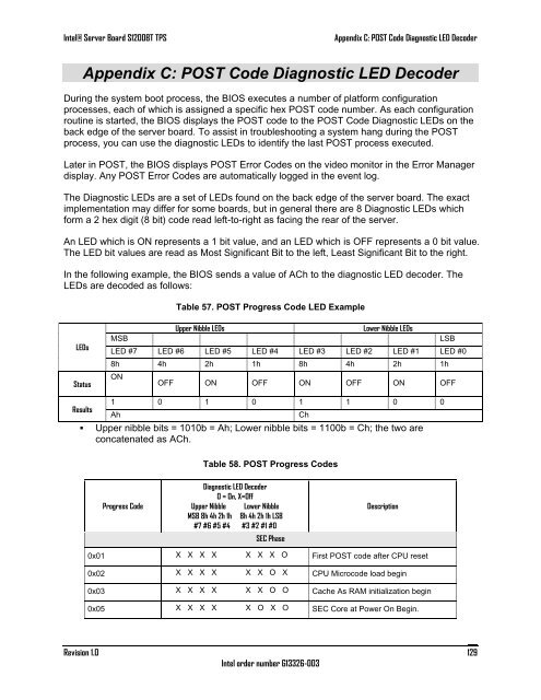
In the following example, the BIOS sends a value of ACh to the diagnostic LED decoder. The<br />
LEDs are decoded as follows:<br />
Table 57. POST Progress Code LED Example<br />
LEDs<br />
Status<br />
Upper Nibble LEDs<br />
Lower Nibble LEDs<br />
MSB<br />
LSB<br />
LED #7 LED #6 LED #5 LED #4 LED #3 LED #2 LED #1 LED #0<br />
8h 4h 2h 1h 8h 4h 2h 1h<br />
ON<br />
OFF ON OFF ON OFF ON OFF<br />
Results<br />
1 0 1 0 1 1 0 0<br />
Ah<br />
• Upper nibble bits = 1010b = Ah; Lower nibble bits = 1100b = Ch; the two are<br />
concatenated as ACh.<br />
Ch<br />
Table 58. POST Progress Codes<br />
Progress Code<br />
Diagnostic LED Decoder<br />
O = On, X=Off<br />
Upper Nibble Lower Nibble<br />
MSB 8h 4h 2h 1h 8h 4h 2h 1h LSB<br />
#7 #6 #5 #4 #3 #2 #1 #0<br />
SEC Phase<br />
Description<br />
0x01 X X X X X X X O First POST code after CPU reset<br />
0x02 X X X X X X O X CPU Microcode load begin<br />
0x03 X X X X X X O O Cache As RAM initialization begin<br />
0x05 X X X X X O X O SEC Core at Power On Begin.<br />
Revision 1.0<br />
<strong>Intel</strong> order number G13326-003<br />
129