Intel Server Board S1200BT - PROconsult Data A/S
Intel Server Board S1200BT - PROconsult Data A/S
Intel Server Board S1200BT - PROconsult Data A/S

Create successful ePaper yourself
Turn your PDF publications into a flip-book with our unique Google optimized e-Paper software.
<strong>Intel</strong>® <strong>Server</strong> <strong>Board</strong> <strong>S1200BT</strong> TPS<br />
Connector/Header Locations and Pin-outs<br />
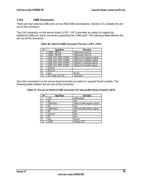
7.5.6 USB Connector<br />
There are four external USB ports on two NIC/USB combinations. Section 5.5.2 details the pinout<br />
of the connector.<br />
Two 2x5 connector on the server board (J1D1, J1E1) provides an option to support an<br />
additional USB port, each connector supporting two USB ports. The following table defines the<br />
pin-out of the connector.<br />
Table 36. Internal USB Connector Pin-out ( J1E1, J1D1)<br />
Pin Signal Name Description<br />
1 USB2_VBUS4 USB power (port 4)<br />
2 USB2_VBUS5 USB power (port 5)<br />
3 USB_ICH_P4N_CONN USB port 4 negative signal<br />
4 USB_ICH_P5N_CONN USB port 5 negative signal<br />
5 USB_ICH_P4P_CONN USB port 4 positive signal<br />
6 USB_ICH_P5P_CONN USB port 5 positive signal<br />
7 Ground<br />
8 Ground<br />
9 Key No pin<br />
10 TP_USB_ICH_NC Test point<br />
One 2x5 connectors on the server board provides an option to support Smart module. The<br />
following table defines the pin-out of the connector:<br />
Table 37. Pin-out of Internal USB Connector for low-profile Smart module (J3F2)<br />
Pin Signal Name Description<br />
1 +5V USB power<br />
2 NC N/A<br />
3 USB <strong>Data</strong> - USB port ## negative signal<br />
4 NC N/A<br />
5 USB <strong>Data</strong> + USB port ## positive signal<br />
6 NC N/A<br />
7 Ground N/A<br />
8 NC N/A<br />
9 Key No pin<br />
10 LED# Activity LED<br />
Revision 1.0<br />
<strong>Intel</strong> order number G13326-003<br />
99