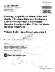
10’ I I I a J P 100 v) v) W a n v) v) W a z E! y IO-’ s E MATCH PARAMETERS = 1.0 psi 1.0 hr = 0.045 = 14 = 10 = 42.45 psia PRESSURE DATA L L PRESSURE-DERIVATIVE DATA - SIMULATIONS 10-2 10.2 lo-’ 100 10’ 102 103 DIMENSIONLESS TIME GROUP. t,/C, Figure 5-88. H-I4/Magenta Third Buildup Log-Log Plot with INTERPRET Simulation 3.0 MATCH PARAMETERS 2.0 - AP f 1.0 psi 1.0 hr PO 0.045 tOiCO 14 CDe2s 10 P’ 106.0 psia , .O 0.0 + DATA - SIMULATION -1.0 0.0 0.5 1 .o 1.5 2.0 2.5 DIMENSIONLESS SUPERPOSITION FUNCTION: FLOW PERIOD 9 114 Figure 5-89. H-l4/Magenta Third Buildup DirnensionIess Homer Plot with INTERPRET Simulation
The complex pressure-skin effects seen during these tests make determination <strong>of</strong> a precise value for the hydraulic head <strong>of</strong> the Magenta at H-14 very difficult. Each buildup period indicated a lower static pressure than the preceding one. The shape <strong>of</strong> the TBU pressure derivative (Figure 5-88) indicates that the static pressure must be lower than the final pressure measured, 11 0.3 psia. The dimensionless Horner plot (Figure 5-89) indicates that 106 psia might be appropriate. Given that the fluid in the hole had a specific gravity <strong>of</strong> 1.2, that the transducer measured an atmospheric pressure <strong>of</strong> 12 psia, and that the transducer was at a depth <strong>of</strong> 401.9 ft, 106 psia corresponds to a pressure <strong>of</strong> about 112 psig at the midpoint <strong>of</strong> the Magenta about 436 ft deep. However, the Magenta response during the three buildup periods raises the question as to what static pressure a fourth buildup period might have shown. A rough interpolation from Magenta water levels at H-3bl and H-4c in 1986 (Saulnier et al., <strong>1987</strong>) indicates that the static pressure at H-14 may have been as low as about 102 psig. In summary, no precise value can be assigned for the hydraulic head <strong>of</strong> the Magenta at H-14. The last measured pressure <strong>of</strong> 116 psig provides a probable maxiumum value, while estimates from H-3 and H-4 water-level data provide a lower estimate <strong>of</strong> about 102 psig. A permanent well completion in the Magenta at H-14 would be required to refine the value further. 5.2.4.2 H-16. At H-16, the Magenta lies from 590.2 to 61 5.6 ft deep (Figure 3-8). The Magenta was cored and reamed on July 28 and 29, <strong>1987</strong>. Following reaming on July 29, <strong>1987</strong>, the drilling fluid in the hole was partially unloaded by airlifting and the DST tool was set in the hole. The Magenta was tested in an interval that extended from 589.2 ft to the then-bottom <strong>of</strong> the hole 620.7 ft deep. Thus, the lower 1 ft <strong>of</strong> the Forty-niner and the upper 5.1 ft <strong>of</strong> the Tamarisk were included in the test interval. These intervals are composed <strong>of</strong> gypsum and anhydrite, however, and were judged to have permeabilities too low to have contributed significantly to the responses observed during testing. Testing was performed on July 30 and 31,<strong>1987</strong>, and consisted <strong>of</strong> two DST flow periods, two buildup periods, and a rising-head slug test (Figure 5-90). The FFL lasted about 22 minutes and was followed by a 466-minute FBU. The SFL lasted about 31 minutes and was followed by a 927-minute SBU. To obtain constant flow rates for buildup analyses, the FFL was divided into two flow periods having flow rates <strong>of</strong> 0.062 and 0.047 gpm, and the SFL was divided into two flow periods having flow rates <strong>of</strong> 0.062 and 0.045 gpm (Table 5-1). The slug test lasted almost 8 hr, during which time about 45% <strong>of</strong> the induced pressure differential dissipated. Descriptions <strong>of</strong> the test instrumentation and the test data are contained in Stensrud et al. (1988). Figure 5-91 shows a log-log plot <strong>of</strong> the FBU data, along with an INTERPRET-generated simulation. The simulation is representative <strong>of</strong> a single-porosity medium with a transmissivity <strong>of</strong> 2.8 x 10⁻² ftZ/day (Table 5-2). Assuming a porosity <strong>of</strong> 20%, a totalsystem compressibility <strong>of</strong> 1.0 x 10⁻⁵ psi-', and a fluid viscosity <strong>of</strong> 1.0 cp, the skin factor for this simulation is -0.4, indicating a very slightly stimulated well. The pressure derivative shows oscillations similar, although with much lower amplitudes, to those observed in the H-14 Magenta SBU and TBU data (Figures 5-87 and 89). Again, these oscillations may be related to periods <strong>of</strong> different hydraulic loading on the Magenta during coring, reaming, and preparation for testing. The decline <strong>of</strong> the pressure derivative at late time clearly shows the effects <strong>of</strong> an overpressure skin. The log-log plot <strong>of</strong> the SBU data (Figure 5-92) looks similar to that <strong>of</strong> the FBU data (Figure 5-91). The SBU simulation is representative <strong>of</strong> a single-porosity medium with a transmissivity <strong>of</strong> 2.8 x 10⁻² ft2/day and a skin factor <strong>of</strong> -0.8 (Table 5-2). The decline in the late-time pressure derivative indicates the continued presence <strong>of</strong> an overpressure skin. Figure 5-93 is a linear-linear plot <strong>of</strong> the Magenta DST sequence with a simulation <strong>of</strong> the entire sequence generated by INTERPRET using the model derived in the FBU analysis. The static formation pressure specified for this simulation was 134.4 psia. Because <strong>of</strong> the continuing dissipation <strong>of</strong> the overpressure skin, the SBU data are generally slightly below the simulation. Otherwise, the match between the observed data and the simulation is excellent. 115
- Page 1 and 2:
SANDIA REPORT SAND87 -0039 UC - 70
- Page 3 and 4:
SAND87-0039 Unlimited Release Print
- Page 5:
a transmissivity of about 7 x 10⁻²
- Page 8 and 9:
5 . TEST OBJECTIVES AND INTERPRETAT
- Page 10 and 11:
3-18 3-19 3-20 3-21 3-22 3-23 3-24
- Page 12 and 13:
5-35 H-l5/Culebra Drillstem and Slu
- Page 14 and 15:
5-78 5-79 5-80 5-81 5-82 5-83 5-84
- Page 16 and 17:
A-2 A-3 A4 A-5 A-6 Single-Porosity
- Page 18 and 19:
'H-6 o DOE-2 OHIPP-13 OAIPP 12 OH-1
- Page 20 and 21:
WlPP site. The aggregate thickness
- Page 22 and 23:
deep. The gamma-ray log used to gui
- Page 24 and 25:
3347.11 ft \ - -12.25-inch HOLE -8.
- Page 26 and 27:
~ 3409.6 n __ - - HOLOCENE DEPOSITS
- Page 28 and 29:
Ylf M (t -1wt 5 n nch REAMED BOREHO
- Page 30 and 31:
3418.96 n 7.875-inch REAMED BOREHOL
- Page 32 and 33:
2.375-inch TUBING 4.5-inch. 9.5 Ibl
- Page 34 and 35:
WELL CASING 2.375-inch TUBING TEST-
- Page 36 and 37:
1.5-Inch GALVANIZED PIPE WELL CASIN
- Page 38 and 39:
I I I I PRE-TEST STATIC PRESSURE i/
- Page 40 and 41:
(or areal extent) of the aquifer on
- Page 42 and 43:
:7001 J EQUILIBRATION / r.. .......
- Page 44 and 45:
Once straddle tests proved impossib
- Page 46 and 47:
1300 c - J PRE-TEST PRESSURE IN TES
- Page 48 and 49:
- < a m L: * m 3 L a I Start Date:
- Page 50 and 51:
uildups were caused by the natural
- Page 52 and 53:
TABLE 5-1 EFFECTIVE DST FLOW RATES
- Page 54 and 55:
TABLE 5-2 SUMMARY OF NON-CULEBRA SI
- Page 56 and 57:
simulation shown, however, uses a t
- Page 58 and 59:
1 .o 0.9 0.8 p' = 79.08 paig pi = 6
- Page 60 and 61:
~ ~~ TABLE 5-3 SUMMARY OF CULEBRA S
- Page 62 and 63:
Two factors raised questions about
- Page 64 and 65: 102 I I 1 1 1 W K 3 v) v) W K n v)
- Page 66 and 67: 5.2.2.21 below) and DOE-2 (Beauheim
- Page 68 and 69: ..A 225 - PRESSURE ABOVE TEST INTER
- Page 70 and 71: 10' n ui K 3 v) v) W a n v) v) 100
- Page 72 and 73: 10' MATCH PARAMETERS O n w a 3 v) v
- Page 74 and 75: ..CI__._._..__....__.I 5.2.2.6 H-15
- Page 76 and 77: 8.0 1 I I I MATCH PARAMETERS AP 1.0
- Page 78 and 79: - 200 150 5 - EQUILIBRATION \Feu 'S
- Page 80 and 81: 4.0 1 I 1 1 3.0 I n 2.0 1 .o 0.0 0.
- Page 82 and 83: 1.0 0.9 0.8 0.7 0.6 0 0.5 0.4 0.3 0
- Page 84 and 85: 3.0 .hl c El2 2.0 . v n I P 1 .o MA
- Page 86 and 87: EI€3- 0.9 "O I OOATA - TYPE CURVE
- Page 88 and 89: 4.0 I I I 3.0 MATCH PARAMETERS AP =
- Page 90 and 91: 1 .o 0.9 0.8 0.7 1 MATCH PARAMETERS
- Page 92 and 93: 1 .o 0.9 0.8 0.7 0.6 0 2 0.5 I 0.4
- Page 94 and 95: 1.0, 0 I 0.9 0.8 0.7 0.6 0.5 0.4 MA
- Page 96 and 97: P-15 was bailed on four occasions i
- Page 98 and 99: 1 .o 0.9 0.8 - p’ = 78.93 prig p,
- Page 100 and 101: Two type-curve matches are shown wi
- Page 102 and 103: 0 5 I ELAPSED TIME. hours Figure 5-
- Page 104 and 105: 10’ 1 I I I n a w 5 100 v) v) W a
- Page 106 and 107: MATCH PARAMETERS -ip 10 PSI 150 t 1
- Page 108 and 109: Considering that all other pumping
- Page 110 and 111: I ,EQUILIBRATION BUILDUP Elapsed Ti
- Page 112 and 113: 0 9. w 10’ K =a 100 v) v) W a n v
- Page 116 and 117: ~ ~. SLUG t i /- i 3 Start Date 07
- Page 118 and 119: Figure 5-94 is a log-log plot of th
- Page 120 and 121: was followed by a 92-minute FBU. Th
- Page 122 and 123: 10’ 1 1 1 1 a n w’ a = 100 v) v
- Page 124 and 125: and anhydrite, and were not conside
- Page 126 and 127: 4.0 MATCH PARAMETERS .A. L. 21% 3.0
- Page 128 and 129: Estimates of the static formation p
- Page 130 and 131: 10’ n w 2 100 v) v) w a P v) v) w
- Page 132 and 133: OWIPP-28. 70 OWIPP-27.650 OWIPP-30.
- Page 134 and 135: to Nash Draw where no halite is pre
- Page 136 and 137: observations regarding the potentia
- Page 138 and 139: 7. SUMMARY AND CONCLUSIONS Single-w
- Page 140 and 141: REFERENCES Bachman, G.O. 1984. Regi
- Page 142 and 143: INTERA Technologies, Inc. 1986. WlP
- Page 144 and 145: Stensrud, W.A.; Bame, M.A.; Lantr,
- Page 146 and 147: (A-4)
- Page 148 and 149: distinct value of Coe2s. Pressure-d
- Page 150 and 151: The wellbore storage coefficient is
- Page 152 and 153: where: n = number of normal sets of
- Page 154 and 155: (A-21) and for spherical blocks the
- Page 156 and 157: where: tp* = Vfq, V = total flow pr
- Page 158 and 159: Figure A-5. Semilog Slug-Test Type
- Page 160 and 161: A.4 INTERPRET WELL-TEST INTERPRETAT
- Page 162 and 163: DISTRIBUTION: U. S. Department of E
- Page 164 and 165:
INTERA Technologies, Inc. (9) 6580
- Page 166 and 167:
WlPP Public Reading Room Carlsbad M
- Page 168 and 169:
Nationale Genossenschaft fur die La