Create successful ePaper yourself
Turn your PDF publications into a flip-book with our unique Google optimized e-Paper software.
DEHN – Technical Definitions<br />
Surge Protective Devices (SPDs)<br />
Surge protective devices are devices consisting<br />
mainly of voltage-controlled resistors (varistors,<br />
suppressor diodes) and/or spark gaps (discharge<br />
paths). Surge protective devices are used to protect<br />
other electrical equipment and installations<br />
against impermissibly high surges and/or to<br />
establish equipotential bonding. Surge protective<br />
devices are classified<br />
a) according to their use into<br />
• Surge protective devices for power supply<br />
systems and equipment<br />
(Red/Line product familiy)<br />
for nominal voltage ranges up to 1000 V<br />
– according to EN 61643-11:2007<br />
+ A11:2007 in type 1 /2 / 3 SPDs<br />
– according to IEC 61643-1:2005/-11:2011<br />
in class I / II / III SPDs<br />
• Surge protective devices for IT systems<br />
and equipment<br />
(Yellow/Line product family)<br />
for protecting modern electronic systems in<br />
telecommunications and signal-processing<br />
networks with nominal voltages up to<br />
1000 V a.c. [root-mean-square value (rms)]<br />
and 1500 V d.c. against the indirect and<br />
direct effects of lightning strikes and other<br />
transients.<br />
– according to IEC 61643-21:2009,<br />
EN 61643-21: 2010 and DIN VDE 0845<br />
Part 3-1.<br />
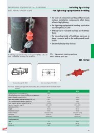
• Isolating spark gaps for earth-termination<br />
systems or equipotential bonding<br />
(Red/Line product family)<br />
• Surge protective devices for use in photovoltaic<br />
installations<br />
(Red/Line product family)<br />
for nominal voltage ranges up to 1500 V<br />
– according to prEN 50539-11:2011 as<br />
type 1 / 2 SPDs<br />
b) according to their impulse current discharge<br />
capacity and protective effect into:<br />
• Lightning current arresters /<br />
Coordinated lightning current arresters<br />
for interference resulting from direct or close<br />
lightning strikes for protecting installations<br />
and equipment [for use at the boundaries<br />
between lightning protection zones (LPZ) 0 A<br />
and 1].<br />
• Surge arresters<br />
for distant lightning strikes, switching overvoltages<br />
as well as electrostatic discharges<br />
for protecting installations, equipment and<br />
terminal devices (for use at the boundaries<br />
downstream of LPZ 0 B ).<br />
• Combined lightning current and surge<br />
arresters<br />
for interference resulting from direct or close<br />
lightning strikes for protecting of installations,<br />
equipment and terminal devices (for<br />
use at the boundaries between LPZ 0 A and 1<br />
as well as 0 A and 2).<br />
Technical data of surge protective devices<br />
The technical data of surge protective devices<br />
comprise information defining their conditions<br />
of use according to<br />
• use (e.g. installation, mains conditions, temperature)<br />
• performance in case of interference (e.g.<br />
impulse current discharge capacity, follow<br />
current extinguishing capability, voltage<br />
protection level, response time)<br />
• performance during operation (e.g. nominal<br />
current, attenuation, insulation resistance)<br />
• performance in case of failure (e.g. backup<br />
fuse, disconnection device, fail-safe, remote<br />
signalling option).<br />
Breaking capacity, follow current extinguishing<br />
capability I fi<br />
The breaking capacity is the uninfluenced<br />
(prospective) rms value of the mains follow current<br />
which can automatically be extinguished<br />
by the surge protective device when connecting<br />
U C . It can be proven in an operating duty test<br />
according to EN 61643-11.<br />
Categories according to IEC 61643-21:2009<br />
(DIN VDE 0845 Part 3-1)<br />
For testing the current carrying capability and<br />
voltage limitation of impulse influences, a variety<br />
of impulse voltages and impulse currents is<br />
described in IEC 61643-21:2009 (DIN VDE 0845<br />
Part 3-1). Table 3 of this standard lists these categories<br />
and provides preferred values. In table 2<br />
of IEC 61643-22 (DIN VDE 0845-3-2) the source<br />
of transients is assigned to the different<br />
impulse categories according to the decoupling<br />
mechanism. Category C2 includes inductive<br />
interference (surges), category D1 galvanic<br />
interference (lightning currents). The relevant<br />
category is specified in the technical data.<br />
DEHN + SÖHNE surge protective devices exceed<br />
the values indicated in the categories. The exact<br />
value of the impulse current carrying capability<br />
is therefore specified by means of the nominal<br />
discharge current (8/20 μs) and the lightning<br />
impulse current (10/350 μs).<br />
Cut-off frequency f G<br />
defines the frequency-dependent behaviour of<br />
an SPD. Cut-off frequencies are equivalent to<br />
the frequency which induces an insertion loss<br />
(a E ) of 3 dB under certain test conditions (see<br />
EN 61643-21:2010). Unless otherwise indicated,<br />
this value refers to a 50 Ω system.<br />
Combined impulse U OC<br />
is generated by a hybrid generator (1.2/50 μs,<br />
8/20 µs) with a ficticious impedance of 2 Ω. The<br />
open-circuit voltage of this generator is defined<br />
as U OC . U OC is a preferred indicator for type 3<br />
SPDs since only these arresters may be tested<br />
with a combined pulse (according to EN 61643-<br />
11).<br />
Degree of protection<br />
The degree of protection (IP) corresponds to the<br />
protection categories in accordance with DIN<br />
EN 60529 (VDE 0470 Part 1).<br />
Disconnecting time t a<br />
is the time passing until the automatic disconnection<br />
from power supply in case of a failure<br />
of the circuit or equipment to be protected. The<br />
disconnecting time is an application-specific<br />
value resulting from the intensity of the fault<br />
current and the characteristics of the protective<br />
device.<br />
Energy coordination of SPDs<br />
is the selective and coordinated effect of the<br />
protection elements (= SPDs) of an overall lightning<br />
and surge protection concept that are connected<br />
one after the other, meaning that the<br />
total load of the lightning impulse current is<br />
divided between the SPDs according to their<br />
energy carrying capability. If energy coordination<br />
is not possible, downstream SPDs are insufficiently<br />
relieved from an energetic point of view<br />
by the upstream SPDs since the upstream SPDs<br />
operate too late, insufficiently or not at all.<br />
Consequently, downstream SPDs as well as terminal<br />
equipment to be protected may be<br />
destroyed. DIN CLC/TS 61643-12:2010 describes<br />
how to verify energy coordination. Spark-gapbased<br />
type 1 SPDs offer considerable advantages<br />
due to their voltage-switching characteristic<br />
(see “WAVE BREAKER FUNCTION“).<br />
Frequency range<br />
represents the transmission range or letthrough<br />
frequency of an SPD depending on the<br />
described attenuation characteristics.<br />
Insertion loss<br />
With a given frequency, the insertion loss of a<br />
surge protective device is defined by the relation<br />
of the voltage value at the installation site<br />
before and after installing the SPD. Unless otherwise<br />
indicated, the value refers to a 50 Ω system.<br />
Integrated backup fuse<br />
According to the product standard<br />
for SPDs, overcurrent protective<br />
devices / backup fuses are to<br />
be used. This, however, requires<br />
additional space in the distribution board, additional<br />
cable lengths, which should be as short<br />
as possible according to DIN VDE 0100-534,<br />
additional installation time (and costs) and<br />
dimensioning of the backup fuse. An arrester<br />
backup fuse integrated in the SPD ideally suited<br />
for the impulse current load eliminates these<br />
disadvantages. The space gain, lower wiring<br />
effort, integrated fuse monitoring and the<br />
increased protective effect due to shorter connecting<br />
cables are considerable advantages of<br />
this concept which is implemented in the<br />
DEHNvenCI, DEHNbloc Maxi S, DEHNguard …<br />
CI and V(A) NH product families.<br />
LifeCheck ®<br />
Repeated discharges processes with values be -<br />
yond the specification of the device may overload<br />
SPDs used in IT systems. In order to ensure<br />
a high system availability, SPDs should therefore<br />
be subject to systematic tests. LifeCheck<br />
allows quick and easy SPD testing (refer also to<br />
page 179).<br />
8 www.dehn.de


