You also want an ePaper? Increase the reach of your titles
YUMPU automatically turns print PDFs into web optimized ePapers that Google loves.
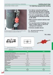
SPDs for Information Technology Systems<br />
Cate- Type of Impulse Impulse Minimum quan- Test<br />
gory test voltage current tity of impulses for<br />
C1 0.5 kV or 0.25 kA or 300<br />
1 kV, 1.2/50 μs 0.5 kA, 8/20 μs<br />
C2 steep 2 kV, 4 kV, 1 kA, 2 kA 10<br />
rate of or 10 kV, or 5 kA,<br />
rise 1.2/50 μs 8/20 μs<br />
C3 ≥ 1 kV, 10 A, 25 A 300<br />
1 kV/μs or 100 A,<br />
10/1000 μs<br />
Surge arrester<br />
D1 high ≥ 1 kV 0.5 kA, 1 kA 2<br />
energy or 2.5 kA, *)<br />
10/350 μs<br />
General<br />
The surge protection components of the arresters do not contain any<br />
radioactive isotopes and consist of at least one voltage-limiting or voltage-switching<br />
component and, in some cases, also of additional overcurrent-limiting<br />
components. Multi-stage arresters must be designed without<br />
blind spots. This means that it must be ensured that the different protection<br />
stages are fully coordinated with one another. Otherwise the protection<br />
stages will not reliably trip and cause faults in the protective<br />
device.<br />
Arrester selection<br />
The following must be observed when selecting arresters:<br />
– Protective effect [Yellow/Line SPD class (discharge capacity and voltage<br />
protection level)]<br />
– System parameters (system voltage, nominal current and transmission<br />
parameters)<br />
– Installations environment (design, connection conditions and approvals)<br />
The selection guide according to interface/signal on pages 158 to 176<br />
facilitates the selection of the right arrester.<br />
Relevant product standard for arresters:<br />
IEC / EN 61643-21<br />
Low-voltage surge protective devices – Part 21: Surge protective devices<br />
connected to telecommunications and signalling networks – Performance<br />
requirements and testing methods<br />
Discharge capacity<br />
According to IEC / EN 61643-21 arresters must be tested with at least<br />
one impulse voltage and impulse current from the above table with the<br />
specified quantity of impulses. Further tests may be performed – even<br />
with different impulse values or quantities. The max. voltage protection<br />
level measured during the test(s) at the output of the device is specified<br />
as voltage protection level U p . Category C represents particularly interference<br />
pulses with a steep rate of rise and low energy, while interference<br />
pulses of category D are supposed to simulate high energy loads<br />
caused by injected partial lightning currents. The relevant category is<br />
specified in the technical data of the arresters [see discharge capacity<br />
(I n , I imp ) and voltage protection level (U p )].<br />
*) Lightning current arrester / Combined lightning current and surge arrester<br />
Voltage and current impulses (preferred values) for determining the voltage-limiting<br />
characteristics (excerpt from Table 3 of IEC / EN 61643-21)<br />
Immunity of terminal equipment to be protected<br />
When testing arresters for electromagnetic compatibility (EMC), electrical<br />
and electronic equipment (devices) must have a certain immunity<br />
against conducted pulse interferences (surges). The requirements on the<br />
immunity and the test set-up are described in EN 61000-4-5.<br />
Since the devices are used in different electromagnetic environments,<br />
they must have different immunities. The immunity of a device depends<br />
on the test level. To classify the different immunities of terminal equipment,<br />
test levels are subdivided into four different levels (1 to 4). Test<br />
level 1 places the lowest requirement on the immunity of terminal equipment.<br />
The test level is specified in the arrester documentation or can be<br />
requested from the manufacturer of the arrester.<br />
Test levels<br />
according to EN 61000-4-5<br />
Corresponds to charging voltage<br />
of the test generator<br />
1 0.5 kV<br />
2 1 kV<br />
3 2 kV<br />
4 4 kV<br />
Protective effect of arresters<br />
Yellow/Line arresters for use in information technology systems are able<br />
to limit conducted interference to a safe level so that the immunity of the<br />
terminal equipment is not exceeded. For example, an arrester with a letthrough<br />
value below the EMC test values of the terminal device must be<br />
selected for a terminal device tested with test level 2:<br />
Impulse voltage < 1 kV in combination with an impulse current of some<br />
amperes (depending on the coupling network).<br />
www.dehn.de<br />
177