
Create successful ePaper yourself
Turn your PDF publications into a flip-book with our unique Google optimized e-Paper software.
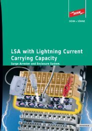
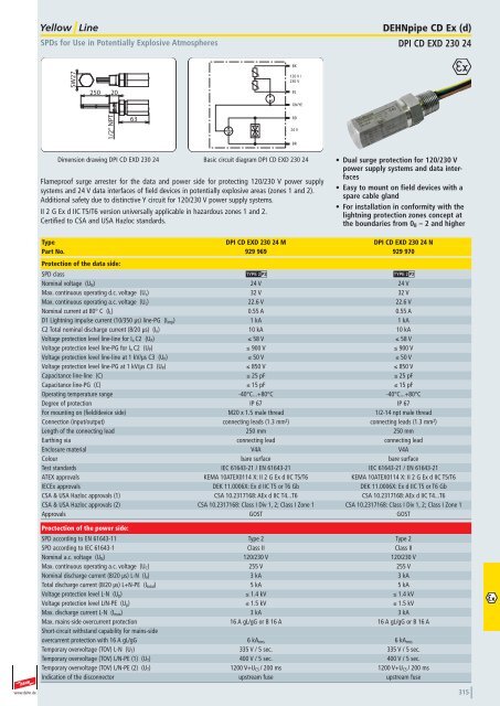
SPDs for Use in Potentially Explosive Atmospheres<br />
DEHNpipe CD Ex (d)<br />
DPI CD EXD 230 24<br />
BK<br />
SW27<br />
250<br />
20<br />
120 V /<br />
230 V<br />
BL<br />
GN/YE<br />
1/2“ NPT<br />
63<br />
RD<br />
24 V<br />
BR<br />
Dimension drawing DPI CD EXD 230 24<br />
Basic circuit diagram DPI CD EXD 230 24<br />
Flameproof surge arrester for the data and power side for protecting 120/230 V power supply<br />
systems and 24 V data interfaces of field devices in potentially explosive areas (zones 1 and 2).<br />
Additional safety due to distinctive Y circuit for 120/230 V power supply systems.<br />
II 2 G Ex d IIC T5/T6 version universally applicable in hazardous zones 1 and 2.<br />
Certified to CSA and USA Hazloc standards.<br />
• Dual surge protection for 120/230 V<br />
power supply systems and data interfaces<br />
• Easy to mount on field devices with a<br />
spare cable gland<br />
• For installation in conformity with the<br />
lightning protection zones concept at<br />
the boundaries from 0 B – 2 and higher<br />
929 969<br />
DPI CD EXD 230 24 M<br />
929 970<br />
DPI CD EXD 230 24 N<br />
DPI CD EXD 230 24 M<br />
929 969<br />
Überspannungsableiter DEHNpipe Ex (d) mit M20x1,5 Aussengewinde<br />
DPI CD EXD 230 24 N<br />
929 970<br />
Überspannungsableiter DEHNpipe Ex (d) mit 1/2"-14 NPT-<br />
Aussengewinde<br />
Type DPI CD EXD 230 24 M DPI CD EXD 230 24 N<br />
Part No. 929 969 929 970<br />
Protection of the data side:<br />
SPD class U U<br />
Nominal voltage (U N ) 24 V 24 V<br />
Max. continuous operating d.c. voltage (U c ) 32 V 32 V<br />
Max. continuous operating a.c. voltage (U c ) 22.6 V 22.6 V<br />
Nominal current at 80° C (I L ) 0.55 A 0.55 A<br />
D1 Lightning impulse current (10/350 μs) line-PG (I imp ) 1 kA 1 kA<br />
C2 Total nominal discharge current (8/20 μs) (I n ) 10 kA 10 kA<br />
Voltage protection level line-line for I n C2 (U P ) ≤ 58 V ≤ 58 V<br />
Voltage protection level line-PG for I n C2 (U P ) ≤ 900 V ≤ 900 V<br />
Voltage protection level line-line at 1 kV/μs C3 (U P ) ≤ 50 V ≤ 50 V<br />
Voltage protection level line-PG at 1 kV/μs C3 (U P ) ≤ 850 V ≤ 850 V<br />
Capacitance line-line (C) ≤ 25 pF ≤ 25 pF<br />
Capacitance line-PG (C) ≤ 15 pF ≤ 15 pF<br />
Operating temperature range -40°C...+80°C -40°C...+80°C<br />
Degree of protection IP 67 IP 67<br />
For mounting on (field/device side) M20 x 1.5 male thread 1/2-14 npt male thread<br />
Connection (input/output) connecting leads (1.3 mm 2 ) connecting leads (1.3 mm 2 )<br />
Length of the connecting lead 250 mm 250 mm<br />
Earthing via connecting lead connecting lead<br />
Enclosure material V4A V4A<br />
Colour bare surface bare surface<br />
Test standards IEC 61643-21 / EN 61643-21 IEC 61643-21 / EN 61643-21<br />
ATEX approvals KEMA 10ATEX0114 X: II 2 G Ex d IIC T5/T6 KEMA 10ATEX0114 X: II 2 G Ex d IIC T5/T6<br />
IECEx approvals DEK 11.0006X: Ex d IIC T5 or T6 Gb DEK 11.0006X: Ex d IIC T5 or T6 Gb<br />
CSA & USA Hazloc approvals (1) CSA 10.2317168: AEx d IIC T4...T6 CSA 10.2317168: AEx d IIC T4...T6<br />
CSA & USA Hazloc approvals (2) CSA 10.2317168: Class I Div 1, 2; Class I Zone 1 CSA 10.2317168: Class I Div 1, 2; Class I Zone 1<br />
Approvals GOST GOST<br />
Proctection of the power side:<br />
SPD according to EN 61643-11 Type 2 Type 2<br />
SPD according to IEC 61643-1 Class II Class II<br />
Nominal a.c. voltage (U N ) 120/230 V 120/230 V<br />
Max. continuous operating a.c. voltage (U C ) 255 V 255 V<br />
Nominal discharge current (8/20 μs) L-N (I n ) 3 kA 3 kA<br />
Total discharge current (8/20 μs) L+N-PE (I total ) 5 kA 5 kA<br />
Voltage protection level L-N (U p ) ≤ 1.4 kV ≤ 1.4 kV<br />
Voltage protection level L/N-PE (U p ) ≤ 1.5 kV ≤ 1.5 kV<br />
Max. discharge current L-N (I max ) 3 kA 3 kA<br />
Max. mains-side overcurrent protection 16 A gL/gG or B 16 A 16 A gL/gG or B 16 A<br />
Short-circuit withstand capability for mains-side<br />
overcurrent protection with 16 A gL/gG 6 kA rms 6 kA rms<br />
Temporary overvoltage (TOV) L-N (U T ) 335 V / 5 sec. 335 V / 5 sec.<br />
Temporary overvoltage (TOV) L/N-PE (1) (U T ) 400 V / 5 sec. 400 V / 5 sec.<br />
Temporary overvoltage (TOV) L/N-PE (2) (U T ) 1200 V+U CS / 200 ms 1200 V+U CS / 200 ms<br />
Indication of the disconnector upstream fuse upstream fuse<br />
www.dehn.de<br />
315