

ASD/LRFD Manual - American Wood Council
ASD/LRFD Manual - American Wood Council
ASD/LRFD Manual - American Wood Council

Create successful ePaper yourself
Turn your PDF publications into a flip-book with our unique Google optimized e-Paper software.
94 M14: SHEAR WALLS AND DIAPHRAGMS<br />
M14.1 General<br />
This Chapter pertains to design of shear walls and<br />
diaphragms. These assemblies, which transfer lateral<br />
forces (wind and seismic) within the structure, are commonly<br />
designed using panel products fastened to framing<br />
members. The use of bracing systems to transfer these<br />
forces is not within the scope of this Chapter.<br />
Shear wall/diaphragm shear capacity is tabulated in<br />
the ANSI/AF&PA Special Design Provisions for Wind and<br />
Seismic (SDPWS) Supplement.<br />
M14.2 Design Principles<br />
Drag Struts/Collectors<br />
The load path for a box-type structure is from the diaphragm<br />
into the shear walls running parallel to the direction<br />
of the load (i.e., the diaphragm loads the shear walls that<br />
support it). Because the diaphragm acts like a long, deep<br />
beam, it loads each of the supporting shear walls evenly<br />
along the length of the walls. However, a wall typically<br />
contains windows and doors.<br />
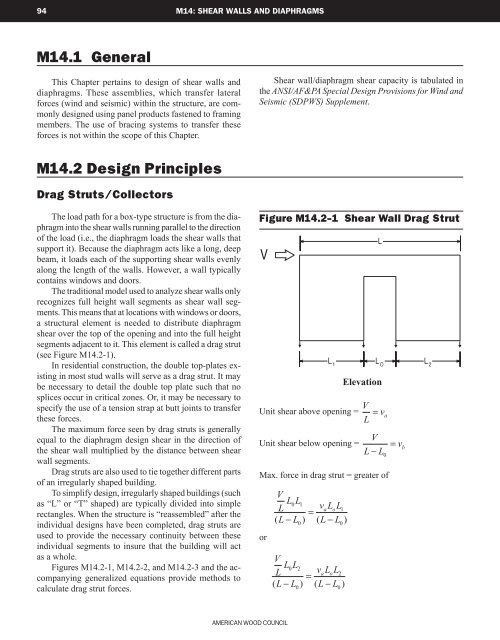
The traditional model used to analyze shear walls only<br />
recognizes full height wall segments as shear wall segments.<br />
This means that at locations with windows or doors,<br />
a structural element is needed to distribute diaphragm<br />
shear over the top of the opening and into the full height<br />
segments adjacent to it. This element is called a drag strut<br />
(see Figure M14.2-1).<br />
In residential construction, the double top-plates existing<br />
in most stud walls will serve as a drag strut. It may<br />
be necessary to detail the double top plate such that no<br />
splices occur in critical zones. Or, it may be necessary to<br />
specify the use of a tension strap at butt joints to transfer<br />
these forces.<br />
The maximum force seen by drag struts is generally<br />
equal to the diaphragm design shear in the direction of<br />
the shear wall multiplied by the distance between shear<br />
wall segments.<br />
Drag struts are also used to tie together different parts<br />
of an irregularly shaped building.<br />
To simplify design, irregularly shaped buildings (such<br />
as “L” or “T” shaped) are typically divided into simple<br />
rectangles. When the structure is “reassembled” after the<br />
individual designs have been completed, drag struts are<br />
used to provide the necessary continuity between these<br />
individual segments to insure that the building will act<br />
as a whole.<br />
Figures M14.2-1, M14.2-2, and M14.2-3 and the accompanying<br />
generalized equations provide methods to<br />
calculate drag strut forces.<br />
Figure M14.2-1 Shear Wall Drag Strut<br />
V<br />
Unit shear above opening = V = v a<br />
L<br />
Unit shear below opening =<br />
V<br />
L − L<br />
Max. force in drag strut = greater of<br />
or<br />
V<br />
L L L 0 1<br />
vaLo<br />
L1<br />
=<br />
( L − L ) ( L − L )<br />
0<br />
V<br />
L L L 0 2<br />
vaLo<br />
L2<br />
=<br />
( L − L ) ( L − L )<br />
0<br />
0<br />
0<br />
L<br />
L 1<br />
L O<br />
L 2<br />
Elevation<br />
0<br />
=<br />
v b<br />
<strong>American</strong> <strong>Wood</strong> <strong>Council</strong>


