

ASD/LRFD Manual - American Wood Council
ASD/LRFD Manual - American Wood Council
ASD/LRFD Manual - American Wood Council

Create successful ePaper yourself
Turn your PDF publications into a flip-book with our unique Google optimized e-Paper software.
<strong>ASD</strong>/<strong>LRFD</strong> MANUAL FOR ENGINEERED <strong>Wood</strong> Construction<br />
125<br />
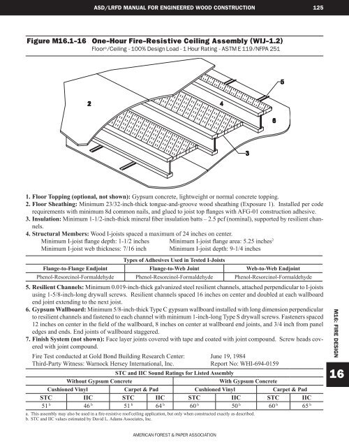
Figure M16.1-16 One-Hour Fire-Resistive Ceiling Assembly (WIJ-1.2)<br />
Floor a /Ceiling - 100% Design Load - 1 Hour Rating - ASTM E 119/NFPA 251<br />
1. Floor Topping (optional, not shown): Gypsum concrete, lightweight or normal concrete topping.<br />
2. Floor Sheathing: Minimum 23/32-inch-thick tongue-and-groove wood sheathing (Exposure 1). Installed per code<br />
requirements with minimum 8d common nails, and glued to joist top flanges with AFG-01 construction adhesive.<br />
3. Insulation: Minimum 1-1/2-inch-thick mineral fiber insulation batts – 2.5 pcf (nominal), supported by resilient channels.<br />
4. Structural Members: <strong>Wood</strong> I-joists spaced a maximum of 24 inches on center.<br />
Minimum I-joist flange depth: 1-1/2 inches Minimum I-joist flange area: 5.25 inches 2<br />
Minimum I-joist web thickness: 7/16 inch Minimum I-joist depth: 9-1/4 inches<br />
Types of Adhesives Used in Tested I-Joists<br />
Flange-to-Flange Endjoint Flange-to-Web Joint Web-to-Web Endjoint<br />
Phenol-Resorcinol-Formaldehyde Phenol-Resorcinol-Formaldehyde Phenol-Resorcinol-Formaldehyde<br />
5. Resilient Channels: Minimum 0.019-inch-thick galvanized steel resilient channels, attached perpendicular to I-joists<br />
using 1-5/8-inch-long drywall screws. Resilient channels spaced 16 inches on center and doubled at each wallboard<br />
end joint extending to the next joist.<br />
6. Gypsum Wallboard: Minimum 5/8-inch-thick Type C gypsum wallboard installed with long dimension perpendicular<br />
to resilient channels and fastened to each channel with minimum 1-inch-long Type S drywall screws. Fasteners spaced<br />
12 inches on center in the field of the wallboard, 8 inches on center at wallboard end joints, and 3/4 inch from panel<br />
edges and ends. End joints of wallboard staggered.<br />
7. Finish System (not shown): Face layer joints covered with tape and coated with joint compound. Screw heads covered<br />
with joint compound.<br />
Fire Test conducted at Gold Bond Building Research Center: June 19, 1984<br />
Third-Party Witness: Warnock Hersey International, Inc.<br />
Report No: WHI-694-0159<br />
STC and IIC Sound Ratings for Listed Assembly<br />
Without Gypsum Concrete<br />
With Gypsum Concrete<br />
Cushioned Vinyl Carpet & Pad Cushioned Vinyl Carpet & Pad<br />
STC IIC STC IIC STC IIC STC IIC<br />
51 b 46 b 51 b 64 b 60 b 50 b 60 b 65 b<br />
a. This assembly may also be used in a fire-resistive roof/ceiling application, but only when constructed exactly as described.<br />
b. STC and IIC values estimated by David L. Adams Associates, Inc.<br />
M16: FIRE DESIGN<br />
16<br />
<strong>American</strong> Forest & paper association


