maxon
maxon
maxon

You also want an ePaper? Increase the reach of your titles
YUMPU automatically turns print PDFs into web optimized ePapers that Google loves.
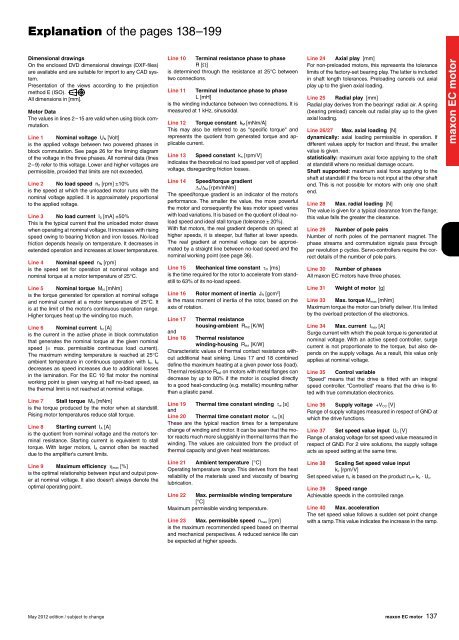
Explanation of the pages 138–199Dimensional drawingsOn the enclosed DVD dimensional drawings (DXF-files)are available and are suitable for import to any CAD system.Presentation of the views according to the projectionmethod E (ISO).All dimensions in [mm].Motor DataThe values in lines 2 – 15 are valid when using block commutation.Line 1 Nominal voltage U N [Volt]is the applied voltage between two powered phases inblock commutation. See page 26 for the timing diagramof the voltage in the three phases. All nominal data (lines2 – 9) refer to this voltage. Lower and higher voltages arepermissible, provided that limits are not exceeded.Line 2 No load speed n 0 [rpm] ±10%is the speed at which the unloaded motor runs with thenominal voltage applied. It is approximately proportionalto the applied voltage.Line 3 No load current I 0 [mA] ±50%This is the typical current that the unloaded motor drawswhen operating at nominal voltage. It increases with risingspeed owing to bearing friction and iron losses. No-loadfriction depends heavily on temperature. It decreases inextended operation and increases at lower temperatures.Line 4 Nominal speed n N [rpm]is the speed set for operation at nominal voltage andnominal torque at a motor temperature of 25°C.Line 5 Nominal torque M N [mNm]is the torque generated for operation at nominal voltageand nominal current at a motor temperature of 25°C. Itis at the limit of the motor's continuous operation range.Higher torques heat up the winding too much.Line 6 Nominal current I N [A]is the current in the active phase in block commutationthat generates the nominal torque at the given nominalspeed (= max. permissible continuous load current).The maximum winding temperature is reached at 25°Cambient temperature in continuous operation with I N. I Ndecreases as speed increases due to additional lossesin the lamination. For the EC 10 flat motor the nominalworking point is given varying at half no-load speed, asthe thermal limit is not reached at nominal voltage.Line 7 Stall torque M H [mNm]is the torque produced by the motor when at standstill.Rising motor temperatures reduce stall torque.Line 8 Starting current I A [A]is the quotient from nominal voltage and the motor's terminalresistance. Starting current is equivalent to stalltorque. With larger motors, I A cannot often be reacheddue to the amplifier's current limits.Line 9 Maximum efficiency max [%]is the optimal relationship between input and output powerat nominal voltage. It also doesn't always denote theoptimal operating point.Line 10 Terminal resistance phase to phaseR []is determined through the resistance at 25°C betweentwo connections.Line 11 Terminal inductance phase to phaseL [mH]is the winding inductance between two connections. It ismeasured at 1 kHz, sinusoidal.Line 12 Torque constant k M [mNm/A]This may also be referred to as "specific torque" andrepresents the quotient from generated torque and applicablecurrent.Line 13 Speed constant k n [rpm/V]indicates the theoretical no load speed per volt of appliedvoltage, disregarding friction losses.Line 14 Speed/torque gradient n/ M [rpm/mNm]The speed/torque gradient is an indicator of the motor'sperformance. The smaller the value, the more powerfulthe motor and consequently the less motor speed varieswith load variations. It is based on the quotient of ideal noloadspeed and ideal stall torque (tolerance ± 20%).With flat motors, the real gradient depends on speed: athigher speeds, it is steeper, but flatter at lower speeds.The real gradient at nominal voltage can be approximatedby a straight line between no-load speed and thenominal working point (see page 36).Line 15 Mechanical time constant m [ms]is the time required for the rotor to accelerate from standstillto 63% of its no-load speed.Line 16 Rotor moment of inertia J R [gcm 2 ]is the mass moment of inertia of the rotor, based on theaxis of rotation.Line 17andLine 18Thermal resistancehousing-ambient R th2 [K/W]Thermal resistancewinding-housing R th1 [K/W]Characteristic values of thermal contact resistance withoutadditional heat sinking. Lines 17 and 18 combineddefine the maximum heating at a given power loss (load).Thermal resistance R th2 on motors with metal flanges candecrease by up to 80% if the motor is coupled directlyto a good heat-conducting (e.g. metallic) mounting ratherthan a plastic panel.Line 19 Thermal time constant winding w [s]andLine 20 Thermal time constant motor m [s]These are the typical reaction times for a temperaturechange of winding and motor. It can be seen that the motorreacts much more sluggishly in thermal terms than thewinding. The values are calculated from the product ofthermal capacity and given heat resistances.Line 21 Ambient temperature [°C]Operating temperature range. This derives from the heatreliability of the materials used and viscosity of bearinglubrication.Line 22 Max. permissible winding temperature[°C]Maximum permissible winding temperature.Line 23 Max. permissible speed n max [rpm]is the maximum recommended speed based on thermaland mechanical perspectives. A reduced service life canbe expected at higher speeds.Line 24 Axial play [mm]For non-preloaded motors, this represents the tolerancelimits of the factory-set bearing play. The latter is includedin shaft length tolerances. Preloading cancels out axialplay up to the given axial loading.Line 25 Radial play [mm]Radial play derives from the bearings' radial air. A spring(bearing preload) cancels out radial play up to the givenaxial loading.Line 26/27 Max. axial loading [N]dynamically: axial loading permissible in operation. Ifdifferent values apply for traction and thrust, the smallervalue is given.statistically: maximum axial force applying to the shaftat standstill where no residual damage occurs.Shaft supported: maximum axial force applying to theshaft at standstill if the force is not input at the other shaftend. This is not possible for motors with only one shaftend.Line 28 Max. radial loading [N]The value is given for a typical clearance from the flange;this value falls the greater the clearance.Line 29 Number of pole pairsNumber of north poles of the permanent magnet. Thephase streams and commutation signals pass throughper revolution p cycles. Servo-controllers require the correctdetails of the number of pole pairs.Line 30 Number of phasesAll <strong>maxon</strong> EC motors have three phases.Line 31Weight of motor [g]Line 33 Max. torque M max [mNm]Maximum torque the motor can briefly deliver. It is limitedby the overload protection of the electronics.Line 34 Max. current I max [A]Surge current with which the peak torque is generated atnominal voltage. With an active speed controller, surgecurrent is not proportionate to the torque, but also dependson the supply voltage. As a result, this value onlyapplies at nominal voltage.Line 35 Control variable“Speed“ means that the drive is fitted with an integralspeed controller. “Controlled“ means that the drive is fittedwith true commutation electronics.Line 36 Supply voltage +V CC [V]Range of supply voltages measured in respect of GND atwhich the drive functions.Line 37 Set speed value input U C [V]Range of analog voltage for set speed value measured inrespect of GND. For 2 wire solutions, the supply voltageacts as speed setting at the same time.Line 38 Scaling Set speed value inputk c [rpm/V]Set speed value n c is based on the product n c= k c · U c.Line 39 Speed rangeAchievable speeds in the controlled range.Line 40 Max. accelerationThe set speed value follows a sudden set point changewith a ramp. This value indicates the increase in the ramp.<strong>maxon</strong> EC motorMay 2012 edition / subject to change<strong>maxon</strong> EC motor137