- Page 1 and 2: Program 2012/13High Precision Drive
- Page 3: Welcome to 4-15maxon motormaxon sel
- Page 6 and 7: maxon manufacturing company in Germ
- Page 8 and 9: Develop,Automate,Test.8
- Page 10 and 11: maxonQuality AssuranceOne of maxon
- Page 12: Where are maxonmotors used today?Ou
- Page 15 and 16: maxon sensorEncoders, DC tachos and
- Page 17 and 18: Selection Guidemaxon gear / maxon s
- Page 19 and 20: GearsGS 12 A 208GP 13 K 209GP 13 A
- Page 21: GearsGS 12 A 208GP 13 K 209GP 13 A
- Page 24 and 25: maxon DC motormaxon DC motorTechnol
- Page 26 and 27: maxon EC motormaxon EC motor ironle
- Page 28 and 29: maxon EC motormaxon EC motor iron-c
- Page 30 and 31: maxon gearTechnology - short and to
- Page 32 and 33: maxon sensorTechnology - short and
- Page 34 and 35: maxon motor controlmaxon motor cont
- Page 36 and 37: maxon DC motor and maxon EC motorKe
- Page 40 and 41: Tolerancesmaxon motorTolerances mus
- Page 42 and 43: maxon motorRegulated servo drivesIn
- Page 44 and 45: maxon e-mediamaxon motorVisit us on
- Page 46 and 47: maxon Conversion Tablesmaxon motorG
- Page 48 and 49: maxon Standard Specificationmaxon D
- Page 50 and 51: maxon DC motorRE 6 6 mm, Precious M
- Page 52 and 53: maxon DC motorRE 10 10 mm, Precious
- Page 54 and 55: maxon DC motorRE 10 10 mm, Precious
- Page 56 and 57: maxon DC motorRE 13 13 mm, Precious
- Page 58 and 59: maxon DC motorRE 13 13 mm, Precious
- Page 60 and 61: maxon DC motorRE 13 13 mm, Precious
- Page 62 and 63: maxon DC motorRE 13 13 mm, Precious
- Page 64 and 65: maxon DC motorRE 13 13 mm, Graphite
- Page 66 and 67: maxon DC motorRE 13 13 mm, Graphite
- Page 68 and 69: maxon DC motorRE 13 13 mm, Graphite
- Page 70 and 71: maxon DC motorRE 13 13 mm, Graphite
- Page 72 and 73: maxon DC motorRE 16 16 mm, Precious
- Page 74 and 75: maxon DC motorRE 16 16 mm, Precious
- Page 76 and 77: maxon DC motorRE 16 16 mm, Graphite
- Page 78 and 79: maxon DC motorRE 25 25 mm, Graphite
- Page 80 and 81: maxon DC motorRE 30 30 mm, Graphite
- Page 82 and 83: maxon DC motorRE 40 40 mm, Graphite
- Page 84 and 85: maxon DC motorRE 65 65 mm, Graphite
- Page 86 and 87: maxon A-max programThe economically
- Page 88 and 89:
maxon DC -max motor-max 12 12 mm, P
- Page 90 and 91:
maxon DC -max motor-max 16 16 mm, P
- Page 92 and 93:
maxon DC -max motor-max 16 16 mm, G
- Page 94 and 95:
maxon DC -max motor-max 19 19 mm, P
- Page 96 and 97:
maxon DC -max motor-max 19 19 mm, G
- Page 98 and 99:
maxon DC -max motor-max 22 22 mm, P
- Page 100 and 101:
maxon DC -max motor-max 22 22 mm, G
- Page 102 and 103:
maxon DC -max motor-max 26 26 mm, P
- Page 104 and 105:
maxon DC -max motor-max 26 26 mm, P
- Page 106 and 107:
maxon DC -max motor-max 26 26 mm, G
- Page 108 and 109:
maxon DC -max motor-max 26 26 mm, G
- Page 110 and 111:
maxon DC -max motor-max 32 32 mm, G
- Page 112 and 113:
maxon DC -max motor-max 32 32 mm, G
- Page 114 and 115:
maxon RE-max programThe high-power
- Page 116 and 117:
maxon DC -max motor-max 13 13 mm, P
- Page 118 and 119:
maxon DC -max motor-max 13 13 mm, P
- Page 120 and 121:
maxon DC -max motor-max 17 17 mm, P
- Page 122 and 123:
maxon DC -max motor-max 17 17 mm, G
- Page 124 and 125:
maxon DC -max motor-max 21 21 mm, P
- Page 126 and 127:
maxon DC -max motor-max 21 21 mm, G
- Page 128 and 129:
maxon DC -max motor-max 24 24 mm, P
- Page 130 and 131:
maxon DC -max motor-max 24 24 mm, G
- Page 132 and 133:
maxon DC -max motor-max 29 29 mm, P
- Page 134 and 135:
maxon DC -max motor-max 29 29 mm, G
- Page 136 and 137:
maxon Standard Specificationmaxon E
- Page 138 and 139:
maxon EC motorEC 6 6 mm, brushless,
- Page 140 and 141:
maxon EC motorEC 10 10 mm, brushles
- Page 142 and 143:
maxon EC motorEC 13 13 mm, brushles
- Page 144 and 145:
maxon EC motorEC 13 13 mm, brushles
- Page 146 and 147:
maxon EC motorEC 16 16 mm, brushles
- Page 148 and 149:
maxon EC motorEC 16 16 mm, brushles
- Page 150 and 151:
maxon EC motorEC 22 22 mm, brushles
- Page 152 and 153:
maxon EC motorEC 22 22 mm, brushles
- Page 154 and 155:
maxon EC motorEC 22 22 mm, brushles
- Page 156 and 157:
maxon EC motorEC 32 32 mm, brushles
- Page 158 and 159:
maxon EC motorEC 45 45 mm, brushles
- Page 160 and 161:
maxon EC motorEC 60 60 mm, brushles
- Page 162 and 163:
maxon EC-max programThe “heart”
- Page 164 and 165:
maxon -max-max 16 2-wire 16 mm, bru
- Page 166 and 167:
maxon -max-max 22 22 mm, brushless,
- Page 168 and 169:
maxon -max-max 30 30 mm, brushless,
- Page 170 and 171:
maxon -max-max 40 40 mm, brushless,
- Page 172 and 173:
For your personal notesmaxon motorP
- Page 174 and 175:
maxon EC-4pole programThe “heart
- Page 176 and 177:
maxon EC -4pole motor-4pole 22 22 m
- Page 178 and 179:
maxon EC -4pole motor-4pole 30 30 m
- Page 180 and 181:
maxon flat motorEC 9.2 flat 10 mm,
- Page 182 and 183:
maxon flat motorEC 14 flat 13.6 mm,
- Page 184 and 185:
maxon flat motorEC 20 flat 20 mm, b
- Page 186 and 187:
maxon flat motorEC 20 flat brushles
- Page 188 and 189:
maxon flat motorEC 32 flat 32 mm, b
- Page 190 and 191:
maxon flat motor-i 40 40 mm, brushl
- Page 192 and 193:
maxon flat motorEC 45 flat 42.8 mm,
- Page 194 and 195:
maxon flat motorEC 45 flat 42.8 mm,
- Page 196 and 197:
maxon flat motorEC 45 flat brushles
- Page 198 and 199:
maxon flat motorEC 60 flat 60 mm, b
- Page 200 and 201:
For your personal notesmaxon motorP
- Page 202 and 203:
maxon Standard Specificationmaxon g
- Page 204 and 205:
Planetary Gearhead GP 6 A 6 mm, 0.0
- Page 206 and 207:
maxon gearPlanetary Gearhead GP 10
- Page 208 and 209:
Spur Gearhead GS 12 A 12 mm, 0.01-0
- Page 210 and 211:
Planetary Gearhead GP 13 A 13 mm, 0
- Page 212 and 213:
maxon gearSpur Gearhead GS 16 K 16
- Page 214 and 215:
maxon gearSpur Gearhead GS 16 V 16
- Page 216 and 217:
maxon gearPlanetary Gearhead GP 16
- Page 218 and 219:
Planetary Gearhead GP 16 C 16 mm, 0
- Page 220 and 221:
Planetary Gearhead GP 19 B 19 mm, 0
- Page 222 and 223:
Planetary Gearhead GP 22 B 22 mm, 0
- Page 224 and 225:
Planetary Gearhead GP 22 A 22 mm, 0
- Page 226 and 227:
maxon gearPlanetary Gearhead GP 22
- Page 228 and 229:
maxon gearPlanetary Gearhead GP 22
- Page 230 and 231:
Spur Gearhead GS 24 A 24 mm, 0.1 Nm
- Page 232 and 233:
Planetary Gearhead GP 26 A 26 mm, 0
- Page 234 and 235:
maxon gearPlanetary Gearhead GP 32
- Page 236 and 237:
Planetary Gearhead GP 32 A 32 mm, 0
- Page 238 and 239:
maxon gearPlanetary Gearhead GP 32
- Page 240 and 241:
maxon gearKoaxdrive KD 32 32 mm, 1.
- Page 242 and 243:
maxon gearPlanetary Gearhead GP 42
- Page 244 and 245:
Spur Gearhead GS 45 A 45 mm, 0.5-2.
- Page 246 and 247:
maxon gearPlanetary Gearhead GP 52
- Page 248 and 249:
Planetary Gearhead GP 81 A 81 mm, 2
- Page 250 and 251:
Spindle Drive Basicsmaxon spindle d
- Page 252 and 253:
Spindle Drive GP 16 S Ø16 mm, Metr
- Page 254 and 255:
Spindle Drive GP 22 S Ø22 mm, Metr
- Page 256 and 257:
Spindle Drive GP 32 S Ø32 mm, Metr
- Page 258 and 259:
Spindle Drive Optionsmaxon spindle
- Page 260 and 261:
For your personal notesmaxon motorP
- Page 262 and 263:
Encoder MILE 64 Counts per turn, 3
- Page 264 and 265:
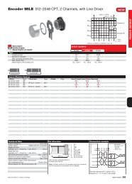
Encoder MILE 800-3200 CPT, 2 Channe
- Page 266 and 267:
Encoder MR Type S, 64-256 CPT, 2 Ch
- Page 268 and 269:
Encoder MR Type M, 32 Counts per tu
- Page 270 and 271:
Encoder MR Type M, 128-512 CPT, 2/3
- Page 272 and 273:
Encoder MR Type ML, 128-1000 CPT, 3
- Page 274 and 275:
Encoder Enc 22 100 Counts per turn,
- Page 276 and 277:
Encoder HEDS 5540 500 Counts per tu
- Page 278 and 279:
Encoder HEDL 5540 500 CPT, 3 Channe
- Page 280 and 281:
Encoder HEDL 5540 500 CPT, 3 Channe
- Page 282 and 283:
Encoder HEDL 9140 500 CPT, 3 Channe
- Page 284 and 285:
Encoder MEnc 13 16 Counts per turn,
- Page 286 and 287:
DC-Tacho DCT 22 0.52 Voltmaxon sens
- Page 288 and 289:
For your personal notesmaxon motorP
- Page 290 and 291:
ESCON Overviewmaxon motor controlTh
- Page 292 and 293:
ESCON Feature Comparison Chartmaxon
- Page 294 and 295:
DECS 50/5 1-Q-EC Amplifier, sensorl
- Page 296 and 297:
DEC Module 50/5 1-Q-EC Amplifiermax
- Page 298 and 299:
1-Q-EC Amplifier Datamaxon motor co
- Page 300 and 301:
1-Q-EC Amplifier Dimensions and con
- Page 302 and 303:
4-Q-EC Amplifier Summarymaxon motor
- Page 304 and 305:
DES 50/5 4-Q-EC Servoamplifiermaxon
- Page 306 and 307:
4-Q-EC Servoamplifier Datamaxon mot
- Page 308 and 309:
4-Q-EC Servoamplifier Dimensions an
- Page 310 and 311:
maxon motor controlEPOS2 Positionin
- Page 312 and 313:
EPOS2 Positioning control unit Data
- Page 314 and 315:
EPOS2 P programmable positioning co
- Page 316 and 317:
EPOS2 P programmable positioning co
- Page 318 and 319:
maxon motor controlPoint to pointTh
- Page 320 and 321:
Summary maxon motor controlmaxon mo
- Page 322 and 323:
Summary maxon motor control accesso
- Page 324 and 325:
MCD EPOS Intelligent compact drivem
- Page 326 and 327:
ProgrammingAccessories MCD EPOS 60
- Page 328 and 329:
Brake AB 20 24 VDC, 0.1 Nmmaxon acc
- Page 330 and 331:
Brake AB 28 24 VDC, 0.4 Nmmaxon acc
- Page 332 and 333:
Brake AB 32 24 VDC, 0.4 Nmmaxon acc
- Page 334 and 335:
Brake AB 44 24 VDC, 2.5 Nmmaxon acc
- Page 336 and 337:
Accessories overviewmaxon accessori
- Page 338 and 339:
For your personal notesmaxon motorP
- Page 340 and 341:
maxon special programRE 15 15 mm, P
- Page 342 and 343:
maxon special programF 2130 30 mm,
- Page 344 and 345:
maxon special programF 2140 40 mm,
- Page 346 and 347:
maxon special programF 2260 60 mm,
- Page 348 and 349:
maxon special programS 2322 22 mm,
- Page 350 and 351:
maxon special programS 2326 26 mm,
- Page 352 and 353:
maxon special programS 2326 26 mm,
- Page 354 and 355:
maxon special programS 2332 32 mm,
- Page 356 and 357:
maxon special programA 2515 15 mm,
- Page 358 and 359:
GM 20 20 mm, Precious Metal Brushes
- Page 360 and 361:
EC 16 16 mm, brushless, 40 Wattmaxo
- Page 362 and 363:
maxon special programEC 22 22 mm, b
- Page 364 and 365:
EC 22 22 mm, brushless, 50 Watt, st
- Page 366 and 367:
maxon maxon special -4pole program-
- Page 368 and 369:
EC 90 flat brushless, 60 Watt, with
- Page 370 and 371:
4-Q-DC Servoamplifier Summarymaxon
- Page 372 and 373:
4-Q-DC Servoamplifier Datamaxon spe
- Page 374 and 375:
4-Q-DC Servoamplifier Dimensions an
- Page 376 and 377:
maxon special designmaxon special d
- Page 378 and 379:
maxon special designmaxon special d
- Page 380 and 381:
For your personal notesmaxon motorP
- Page 382 and 383:
maxon ceramic - Innovative CIM / MI
- Page 384 and 385:
MIM technology — Complex Shapes i
- Page 386 and 387:
maxon Manufacturing Companiesmaxon
- Page 388 and 389:
Americamaxon Sales CompaniesUSA (Ea
- Page 390:
maxon product rangeThe solution is