

Programmable Controllers: Theory and Implementation
Programmable Controllers: Theory and Implementation
Programmable Controllers: Theory and Implementation
- No tags were found...

You also want an ePaper? Increase the reach of your titles
YUMPU automatically turns print PDFs into web optimized ePapers that Google loves.
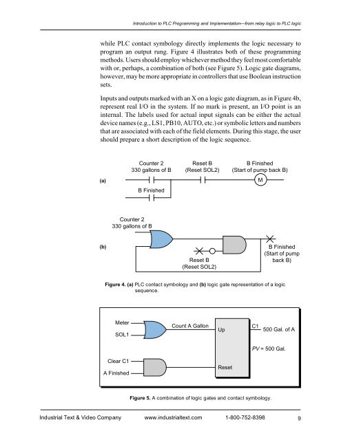
Introduction to PLC Programming <strong>and</strong> <strong>Implementation</strong>—from relay logic to PLC logicwhile PLC contact symbology directly implements the logic necessary toprogram an output rung. Figure 4 illustrates both of these programmingmethods. Users should employ whichever method they feel most comfortablewith or, perhaps, a combination of both (see Figure 5). Logic gate diagrams,however, may be more appropriate in controllers that use Boolean instructionsets.Inputs <strong>and</strong> outputs marked with an X on a logic gate diagram, as in Figure 4b,represent real I/O in the system. If no mark is present, an I/O point is aninternal. The labels used for actual input signals can be either the actualdevice names (e.g., LS1, PB10, AUTO, etc.) or symbolic letters <strong>and</strong> numbersthat are associated with each of the field elements. During this stage, the usershould prepare a short description of the logic sequence.Counter 2330 gallons of BReset B(Reset SOL2)B Finished(Start of pump back B)(a)MB FinishedCounter 2330 gallons of B(b)Reset B(Reset SOL2)B Finished(Start of pumpback B)Figure 4. (a) PLC contact symbology <strong>and</strong> (b) logic gate representation of a logicsequence.MeterSOL1Count A GallonUpC1500 Gal. of APV = 500 Gal.Clear C1A FinishedResetFigure 5. A combination of logic gates <strong>and</strong> contact symbology.Industrial Text & Video Company www.industrialtext.com 1-800-752-83989


