

Programmable Controllers: Theory and Implementation
Programmable Controllers: Theory and Implementation
Programmable Controllers: Theory and Implementation
- No tags were found...

Create successful ePaper yourself
Turn your PDF publications into a flip-book with our unique Google optimized e-Paper software.
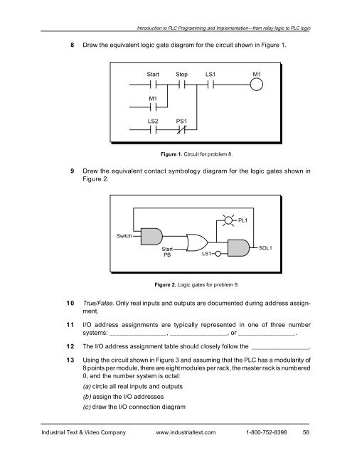
Introduction to PLC Programming <strong>and</strong> <strong>Implementation</strong>—from relay logic to PLC logic8 Draw the equivalent logic gate diagram for the circuit shown in Figure 1.StartStopLS1M1M1LS2PS1Figure 1. Circuit for problem 8.9 Draw the equivalent contact symbology diagram for the logic gates shown inFigure 2.PL1SwitchStartPBLS1SOL1Figure 2. Logic gates for problem 9.10 True/False. Only real inputs <strong>and</strong> outputs are documented during address assignment.11 I/O address assignments are typically represented in one of three numbersystems: __________________, __________________, or __________________.12 The I/O address assignment table should closely follow the __________________.13 Using the circuit shown in Figure 3 <strong>and</strong> assuming that the PLC has a modularity of8 points per module, there are eight modules per rack, the master rack is numbered0, <strong>and</strong> the number system is octal:(a) circle all real inputs <strong>and</strong> outputs(b) assign the I/O addresses(c) draw the I/O connection diagramIndustrial Text & Video Company www.industrialtext.com 1-800-752-839856


