

Programmable Controllers: Theory and Implementation
Programmable Controllers: Theory and Implementation
Programmable Controllers: Theory and Implementation
- No tags were found...

Create successful ePaper yourself
Turn your PDF publications into a flip-book with our unique Google optimized e-Paper software.
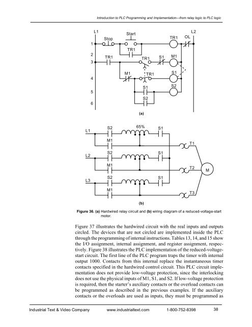
Introduction to PLC Programming <strong>and</strong> <strong>Implementation</strong>—from relay logic to PLC logicL1123StopTR1StartTR1TR1S1TR1M1L2OL4M1TR1S156S1S2S2(a)L1S265%S1M1T1L2S2S1M1T2ML3S2S1M1T3(b)Figure 36. (a) Hardwired relay circuit <strong>and</strong> (b) wiring diagram of a reduced-voltage-startmotor.Figure 37 illustrates the hardwired circuit with the real inputs <strong>and</strong> outputscircled. The devices that are not circled are implemented inside the PLCthrough the programming of internal instructions. Tables 13, 14, <strong>and</strong> 15 showthe I/O assignment, internal assignment, <strong>and</strong> register assignment, respectively.Figure 38 illustrates the PLC implementation of the reduced-voltagestartcircuit. The first line of the PLC program traps the timer with internaloutput 1000. Contacts from this internal replace the instantaneous timercontacts specified in the hardwired control circuit. This PLC circuit implementationdoes not provide low-voltage protection, since the interlockingdoes not use the physical inputs of M1, S1, <strong>and</strong> S2. If low-voltage protectionis required, then the starter’s auxiliary contacts or the overload contacts canbe programmed as described in the previous examples. If the auxiliarycontacts or the overloads are used as inputs, they must be programmed asIndustrial Text & Video Company www.industrialtext.com 1-800-752-839838


