

Programmable Controllers: Theory and Implementation
Programmable Controllers: Theory and Implementation
Programmable Controllers: Theory and Implementation
- No tags were found...

You also want an ePaper? Increase the reach of your titles
YUMPU automatically turns print PDFs into web optimized ePapers that Google loves.
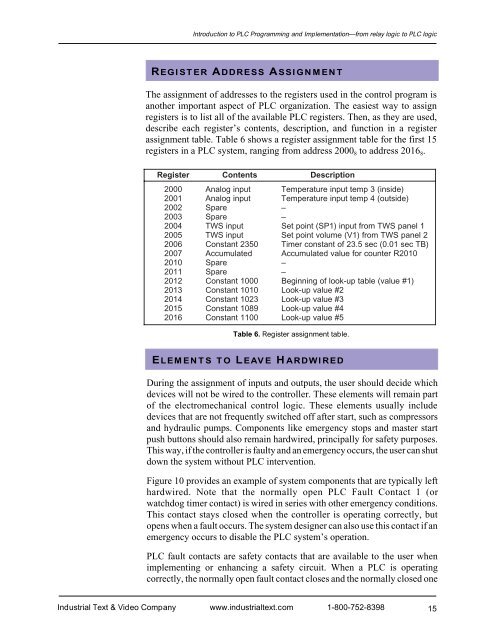
Introduction to PLC Programming <strong>and</strong> <strong>Implementation</strong>—from relay logic to PLC logicREGISTER ADDRESS ASSIGNMENTThe assignment of addresses to the registers used in the control program isanother important aspect of PLC organization. The easiest way to assignregisters is to list all of the available PLC registers. Then, as they are used,describe each register’s contents, description, <strong>and</strong> function in a registerassignment table. Table 6 shows a register assignment table for the first 15registers in a PLC system, ranging from address 2000 8 to address 2016 8 .RegisterContentsDescription2000A nalog inputTemperature input temp 3 (inside)2001A nalog inputTemperature input temp 4 (outside)2002S pare–2003S pare–2004TWS inputSet point (SP1) input from TWS panel 12005TWS inputSet point volume (V1) from TWS panel 22006C onstant 2350Timer constant of 23.5 sec (0.01 sec TB)2007AccumulatedAccumulated value for counter R20102010S pare–2011S pare–2012C onstant 1000Beginning of look-up table (value #1)2013Constant1010Look-up value # 22014Constant1023Look-up value # 32015Constant1089Look-up value # 42016Constant1100Look-up value # 5Table 6. Register assignment table.ELEMENTS TO LEAVE HARDWIREDDuring the assignment of inputs <strong>and</strong> outputs, the user should decide whichdevices will not be wired to the controller. These elements will remain partof the electromechanical control logic. These elements usually includedevices that are not frequently switched off after start, such as compressors<strong>and</strong> hydraulic pumps. Components like emergency stops <strong>and</strong> master startpush buttons should also remain hardwired, principally for safety purposes.This way, if the controller is faulty <strong>and</strong> an emergency occurs, the user can shutdown the system without PLC intervention.Figure 10 provides an example of system components that are typically lefthardwired. Note that the normally open PLC Fault Contact 1 (orwatchdog timer contact) is wired in series with other emergency conditions.This contact stays closed when the controller is operating correctly, butopens when a fault occurs. The system designer can also use this contact if anemergency occurs to disable the PLC system’s operation.PLC fault contacts are safety contacts that are available to the user whenimplementing or enhancing a safety circuit. When a PLC is operatingcorrectly, the normally open fault contact closes <strong>and</strong> the normally closed oneIndustrial Text & Video Company www.industrialtext.com 1-800-752-839815


