

Programmable Controllers: Theory and Implementation
Programmable Controllers: Theory and Implementation
Programmable Controllers: Theory and Implementation
- No tags were found...

You also want an ePaper? Increase the reach of your titles
YUMPU automatically turns print PDFs into web optimized ePapers that Google loves.
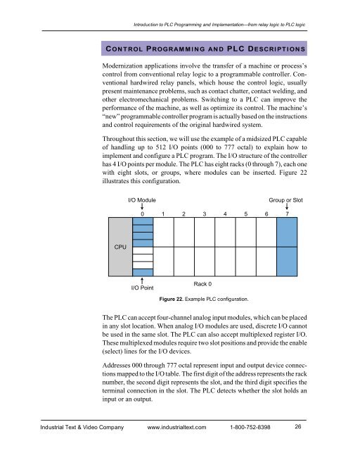
Introduction to PLC Programming <strong>and</strong> <strong>Implementation</strong>—from relay logic to PLC logicCONTROL PROGRAMMING AND PLC DESCRIPTIONSModernization applications involve the transfer of a machine or process’scontrol from conventional relay logic to a programmable controller. Conventionalhardwired relay panels, which house the control logic, usuallypresent maintenance problems, such as contact chatter, contact welding, <strong>and</strong>other electromechanical problems. Switching to a PLC can improve theperformance of the machine, as well as optimize its control. The machine’s“new” programmable controller program is actually based on the instructions<strong>and</strong> control requirements of the original hardwired system.Throughout this section, we will use the example of a midsized PLC capableof h<strong>and</strong>ling up to 512 I/O points (000 to 777 octal) to explain how toimplement <strong>and</strong> configure a PLC program. The I/O structure of the controllerhas 4 I/O points per module. The PLC has eight racks (0 through 7), each onewith eight slots, or groups, where modules can be inserted. Figure 22illustrates this configuration.I/O ModuleGroup or Slot0 1 2 3 4 5 6 7CPUI/O PointRack 0Figure 22. Example PLC configuration.The PLC can accept four-channel analog input modules, which can be placedin any slot location. When analog I/O modules are used, discrete I/O cannotbe used in the same slot. The PLC can also accept multiplexed register I/O.These multiplexed modules require two slot positions <strong>and</strong> provide the enable(select) lines for the I/O devices.Addresses 000 through 777 octal represent input <strong>and</strong> output device connectionsmapped to the I/O table. The first digit of the address represents the racknumber, the second digit represents the slot, <strong>and</strong> the third digit specifies theterminal connection in the slot. The PLC detects whether the slot holds aninput or an output.Industrial Text & Video Company www.industrialtext.com 1-800-752-839826


