

Programmable Controllers: Theory and Implementation
Programmable Controllers: Theory and Implementation
Programmable Controllers: Theory and Implementation
- No tags were found...

Create successful ePaper yourself
Turn your PDF publications into a flip-book with our unique Google optimized e-Paper software.
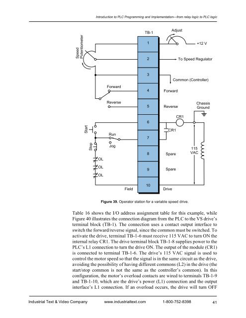
Introduction to PLC Programming <strong>and</strong> <strong>Implementation</strong>—from relay logic to PLC logicSpeedPotentiometerTB-112Adjust+12 VTo Speed RegulatorForward34ForwardCommon (Controller)Reverse5ReverseChassisGround6CR1StartRun7CR1StopOLJog8Spare115VACOLOL9SpareField10DriveFigure 39. Operator station for a variable speed drive.Table 16 shows the I/O address assignment table for this example, whileFigure 40 illustrates the connection diagram from the PLC to the VS drive’sterminal block (TB-1). The connection uses a contact output interface toswitch the forward/reverse signal, since the common must be switched. Toactivate the drive, terminal TB-1-6 must receive 115 VAC to turn ON theinternal relay CR1. The drive terminal block TB-1-8 supplies power to thePLC’s L1 connection to turn the drive ON. The output of the module (CR1)is connected to terminal TB-1-6. The drive’s 115 VAC signal is used tocontrol the motor speed so that the signal is in the same circuit as the drive,avoiding the possibility of having different commons (L2) in the drive (thestart/stop common is not the same as the controller’s common). In thisconfiguration, the motor’s overload contacts are wired to terminals TB-1-9<strong>and</strong> TB-1-10, which are the drive’s power (L1) connection <strong>and</strong> the outputinterface’s L1 connection. If an overload occurs, the drive will turn OFFIndustrial Text & Video Company www.industrialtext.com 1-800-752-839841


