

Programmable Controllers: Theory and Implementation
Programmable Controllers: Theory and Implementation
Programmable Controllers: Theory and Implementation
- No tags were found...

You also want an ePaper? Increase the reach of your titles
YUMPU automatically turns print PDFs into web optimized ePapers that Google loves.
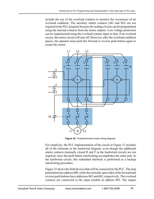
Introduction to PLC Programming <strong>and</strong> <strong>Implementation</strong>—from relay logic to PLC logicinclude the use of the overload contacts to monitor the occurrence of anoverload condition. The auxiliary starter contacts (M1 <strong>and</strong> M2) are notrequired in the PLC program because the sealing circuits can be programmedusing the internal contacts from the motor outputs. Low-voltage protectioncan be implemented using the overload contact input so that, if an overloadoccurs, the motor circuit will turn off. However, after the overload conditionpasses, the operator must push the forward or reverse push button again torestart the motor.L1 L2 L33F1 2 3 1 2 3R23FR2OLT2T1MT3Figure 32. Forward/reverse motor wiring diagram.For simplicity, the PLC implementation of the circuit in Figure 31 includesall of the elements in the hardwired diagram, even though the additionalstarter contacts (normally closed R <strong>and</strong> F in the hardwired circuit) are notrequired, since the push button interlocking accomplishes the same task. Inthe hardwired circuit, this redundant interlock is performed as a backupinterlocking procedure.Figure 33 shows the field devices that will be connected to the PLC. The stoppush button has address 000, while the normally open sides of the forward <strong>and</strong>reverse push buttons have addresses 001 <strong>and</strong> 002, respectively. The overloadcontacts are connected to the input module at address 003. The outputIndustrial Text & Video Company www.industrialtext.com 1-800-752-839834


