

Programmable Controllers: Theory and Implementation
Programmable Controllers: Theory and Implementation
Programmable Controllers: Theory and Implementation
- No tags were found...

You also want an ePaper? Increase the reach of your titles
YUMPU automatically turns print PDFs into web optimized ePapers that Google loves.
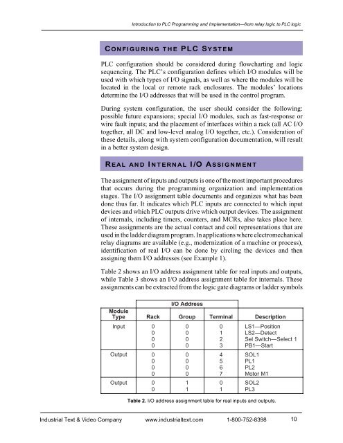
Introduction to PLC Programming <strong>and</strong> <strong>Implementation</strong>—from relay logic to PLC logicCONFIGURING THE PLC SYSTEMPLC configuration should be considered during flowcharting <strong>and</strong> logicsequencing. The PLC’s configuration defines which I/O modules will beused with which types of I/O signals, as well as where the modules will belocated in the local or remote rack enclosures. The modules’ locationsdetermine the I/O addresses that will be used in the control program.During system configuration, the user should consider the following:possible future expansions; special I/O modules, such as fast-response orwire fault inputs; <strong>and</strong> the placement of interfaces within a rack (all AC I/Otogether, all DC <strong>and</strong> low-level analog I/O together, etc.). Consideration ofthese details, along with system configuration documentation, will resultin a better system design.REAL AND INTERNAL I/O ASSIGNMENTThe assignment of inputs <strong>and</strong> outputs is one of the most important proceduresthat occurs during the programming organization <strong>and</strong> implementationstages. The I/O assignment table documents <strong>and</strong> organizes what has beendone thus far. It indicates which PLC inputs are connected to which inputdevices <strong>and</strong> which PLC outputs drive which output devices. The assignmentof internals, including timers, counters, <strong>and</strong> MCRs, also takes place here.These assignments are the actual contact <strong>and</strong> coil representations that areused in the ladder diagram program. In applications where electromechanicalrelay diagrams are available (e.g., modernization of a machine or process),identification of real I/O can be done by circling the devices <strong>and</strong> thenassigning them I/O addresses (see Example 1).Table 2 shows an I/O address assignment table for real inputs <strong>and</strong> outputs,while Table 3 shows an I/O address assignment table for internals. Theseassignments can be extracted from the logic gate diagrams or ladder symbolsModuleTypeRackI/O AddressGroupTerminalDescriptionInput0 0 0 LS1—Position0 0 1 LS2—Detect0 0 2 Sel Switch—Select 10 0 3 PB1—StartOutput0 0 4 SOL10 0 5 PL10 0 6 PL20 0 7 Motor M1Output0 1 0 SOL20 1 1 PL3Table 2. I/O address assignment table for real inputs <strong>and</strong> outputs.Industrial Text & Video Company www.industrialtext.com 1-800-752-839810


