

Programmable Controllers: Theory and Implementation
Programmable Controllers: Theory and Implementation
Programmable Controllers: Theory and Implementation
- No tags were found...

Create successful ePaper yourself
Turn your PDF publications into a flip-book with our unique Google optimized e-Paper software.
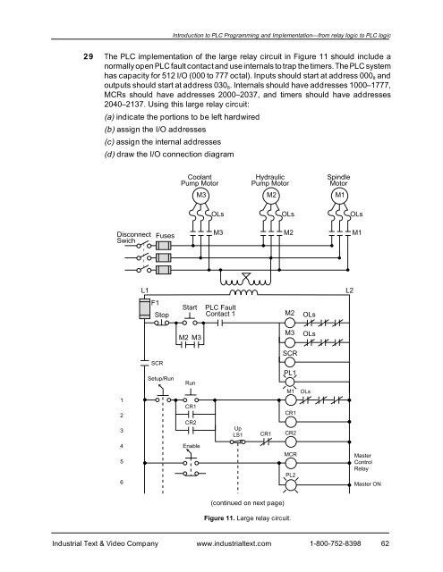
Introduction to PLC Programming <strong>and</strong> <strong>Implementation</strong>—from relay logic to PLC logic29 The PLC implementation of the large relay circuit in Figure 11 should include anormally open PLC fault contact <strong>and</strong> use internals to trap the timers. The PLC systemhas capacity for 512 I/O (000 to 777 octal). Inputs should start at address 000 8 <strong>and</strong>outputs should start at address 030 8 . Internals should have addresses 1000–1777,MCRs should have addresses 2000–2037, <strong>and</strong> timers should have addresses2040–2137. Using this large relay circuit:(a) indicate the portions to be left hardwired(b) assign the I/O addresses(c) assign the internal addresses(d) draw the I/O connection diagramCoolantPump MotorHydraulicPump MotorSpindleMotorM3M2M1OLsOLsOLsDisconnectSwichFusesM3M2M1L1L2F1StopStartPLC FaultContact 1M2OLsM2 M3M3OLsSCRSCR123Setup/RunRunCR1CR2UpLS1CR1PL1M1CR1CR2OLs456EnableMCRPL2MasterControlRelayMaster ON(continued on next page)Figure 11. Large relay circuit.Industrial Text & Video Company www.industrialtext.com 1-800-752-839862


