

Programmable Controllers: Theory and Implementation
Programmable Controllers: Theory and Implementation
Programmable Controllers: Theory and Implementation
- No tags were found...

You also want an ePaper? Increase the reach of your titles
YUMPU automatically turns print PDFs into web optimized ePapers that Google loves.
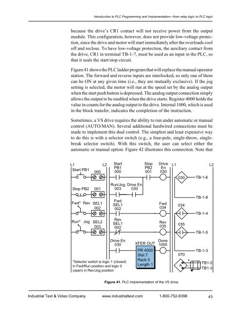
Introduction to PLC Programming <strong>and</strong> <strong>Implementation</strong>—from relay logic to PLC logicbecause the drive’s CR1 contact will not receive power from the outputmodule. This configuration, however, does not provide low-voltage protection,since the drive <strong>and</strong> motor will start immediately after the overloads cooloff <strong>and</strong> reclose. To have low-voltage protection, the auxiliary contact fromthe drive, CR1 in terminal TB-1-7, must be used as an input in the PLC, sothat it seals the start/stop circuit.Figure 41 shows the PLC ladder program that will replace the manual operatorstation. The forward <strong>and</strong> reverse inputs are interlocked, so only one of themcan be ON at any given time (i.e., they are mutually exclusive). If the jogsetting is selected, the motor will run at the speed set by the analog outputwhen the start push button is depressed. The analog output connection simplyallows the output to be enabled when the drive starts. Register 4000 holds thevalue in counts for the analog output to the drive. Internal 1000, which is usedin the block transfer, indicates the completion of the instruction.Sometimes, a VS drive requires the ability to run under automatic or manualcontrol (AUTO/MAN). Several additional hardwired connections must bemade to implement this dual control. The simplest <strong>and</strong> least expensive wayto do this is with a selector switch (e.g., a four-pole, single-throw, singlebreakselector switch). With this switch, the user can select either theautomatic or manual option. Figure 42 illustrates this connection. Note thatL1 L2 StartStop Drive L1 L2PB1PB2 EnStart PB1000 000001 030030 TB-1-6Stop PB2 001Run/Jog003Drive En030Fwd* Rev SEL1002Run*Jog SEL2003FwdSEL1002RevSEL1002Fwd034Rev035034035TB-1-8TB-1-4TB-1-5Drive En030*Selector switch is logic 1 (closed)in Fwd/Run position <strong>and</strong> logic 0(open) in Rev/Jog positionXFER OUTPR 4000Slot 7Rack 0Length 1Done1000070A+–TB-1-3TB1-2TB1-3Figure 41. PLC implementation of the VS drive.Industrial Text & Video Company www.industrialtext.com 1-800-752-839843


