Programmable Controllers: Theory and Implementation
Programmable Controllers: Theory and Implementation
Programmable Controllers: Theory and Implementation
- No tags were found...
Create successful ePaper yourself
Turn your PDF publications into a flip-book with our unique Google optimized e-Paper software.
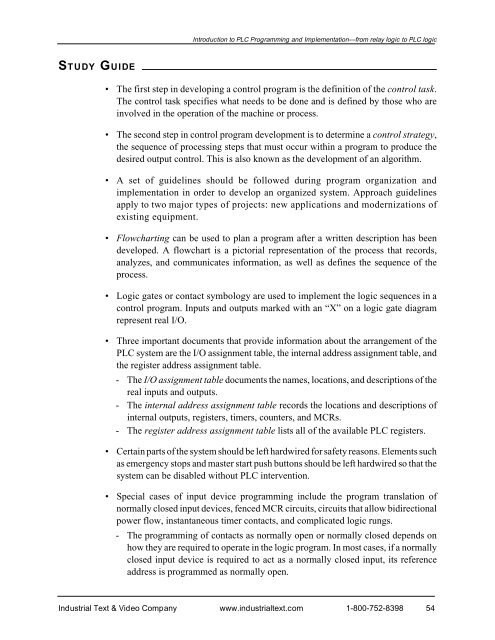
Introduction to PLC Programming <strong>and</strong> <strong>Implementation</strong>—from relay logic to PLC logicSTUDY GUIDE• The first step in developing a control program is the definition of the control task.The control task specifies what needs to be done <strong>and</strong> is defined by those who areinvolved in the operation of the machine or process.• The second step in control program development is to determine a control strategy,the sequence of processing steps that must occur within a program to produce thedesired output control. This is also known as the development of an algorithm.• A set of guidelines should be followed during program organization <strong>and</strong>implementation in order to develop an organized system. Approach guidelinesapply to two major types of projects: new applications <strong>and</strong> modernizations ofexisting equipment.• Flowcharting can be used to plan a program after a written description has beendeveloped. A flowchart is a pictorial representation of the process that records,analyzes, <strong>and</strong> communicates information, as well as defines the sequence of theprocess.• Logic gates or contact symbology are used to implement the logic sequences in acontrol program. Inputs <strong>and</strong> outputs marked with an “X” on a logic gate diagramrepresent real I/O.• Three important documents that provide information about the arrangement of thePLC system are the I/O assignment table, the internal address assignment table, <strong>and</strong>the register address assignment table.- The I/O assignment table documents the names, locations, <strong>and</strong> descriptions of thereal inputs <strong>and</strong> outputs.- The internal address assignment table records the locations <strong>and</strong> descriptions ofinternal outputs, registers, timers, counters, <strong>and</strong> MCRs.- The register address assignment table lists all of the available PLC registers.• Certain parts of the system should be left hardwired for safety reasons. Elements suchas emergency stops <strong>and</strong> master start push buttons should be left hardwired so that thesystem can be disabled without PLC intervention.• Special cases of input device programming include the program translation ofnormally closed input devices, fenced MCR circuits, circuits that allow bidirectionalpower flow, instantaneous timer contacts, <strong>and</strong> complicated logic rungs.- The programming of contacts as normally open or normally closed depends onhow they are required to operate in the logic program. In most cases, if a normallyclosed input device is required to act as a normally closed input, its referenceaddress is programmed as normally open.Industrial Text & Video Company www.industrialtext.com 1-800-752-839854


