

Programmable Controllers: Theory and Implementation
Programmable Controllers: Theory and Implementation
Programmable Controllers: Theory and Implementation
- No tags were found...

You also want an ePaper? Increase the reach of your titles
YUMPU automatically turns print PDFs into web optimized ePapers that Google loves.
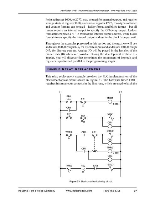
Introduction to PLC Programming <strong>and</strong> <strong>Implementation</strong>—from relay logic to PLC logicPoint addresses 1000 8 to 2777 8 may be used for internal outputs, <strong>and</strong> registerstorage starts at register 3000 8 <strong>and</strong> ends at register 4777 8 . Two types of timer<strong>and</strong> counter formats can be used—ladder format <strong>and</strong> block format—but alltimers require an internal output to specify the ON-delay output. Ladderformat timers place a “T” in front of the internal output address, while blockformat timers specify the internal output address in the block’s output coil.Throughout the examples presented in this section <strong>and</strong> the next, we will useaddresses 000 8 through 027 8 for discrete inputs <strong>and</strong> addresses 030 8 through047 8 for discrete outputs. Analog I/O will be placed in the last slot of themaster rack (0) whenever possible. During the development of these examples,you will discover that sometimes the assignment of internals <strong>and</strong>registers is performed parallel to the programming stages.SIMPLE RELAY REPLACEMENTThis relay replacement example involves the PLC implementation of theelectromechanical circuit shown in Figure 23. The hardware timer TMR1requires instantaneous contacts in the first rung, which are used to latch theL1L2PB1PS1TMR13 secCR1FS1TS1SOL1CR1TMR1CR1LS1SOL2CR2CR1TMR22 secCR3TMR2PS2CR3SOL3Figure 23. Electromechanical relay circuit.Industrial Text & Video Company www.industrialtext.com 1-800-752-839827


