

Programmable Controllers: Theory and Implementation
Programmable Controllers: Theory and Implementation
Programmable Controllers: Theory and Implementation
- No tags were found...

Create successful ePaper yourself
Turn your PDF publications into a flip-book with our unique Google optimized e-Paper software.
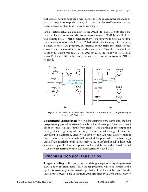
Introduction to PLC Programming <strong>and</strong> <strong>Implementation</strong>—from relay logic to PLC logicthat closes or opens once the timer is enabled), the programmer must use aninternal output to trap the timer, then use the internal’s contact as aninstantaneous contact to drive the timer’s logic.In the electromechanical circuit in Figure 20a, if PB1 <strong>and</strong> LS1 both close, thetimer will start timing <strong>and</strong> the instantaneous contact (TMR1-1) will close,thus sealing PB1. If PB1 is released (OFF), the timer will continue to timebecause the circuit is sealed. Figure 20b illustrates the technique for trappinga timer. In this PLC program, an internal output traps the instantaneouscontact from the circuit’s electromechanical timer. Thus, the contacts fromthis internal drive the timer. If a trap does not exist, the timer will start timingwhen PB1 <strong>and</strong> LS1 both close, but will stop timing as soon as PB1 isreleased.L1PB1LS1L2TMR1PB1LS1InternalTMR1-1InstantaneousTimer ContactInternalTrapCircuitTMR1-2SOL7InternalTMR1TMR1SOL1(a)(b)Figure 20. (a) An instantaneous timer contact in a hardwired circuit <strong>and</strong> (b) a trappedtimer in a PLC circuit.Complicated Logic Rungs. When a logic rung is very confusing, the bestprogramming procedure is to isolate it from the other rungs. Then, reconstructall of the possible logic paths from right to left, starting at the output <strong>and</strong>ending at the beginning of the rung. If a section of a rung, like the onediscussed in Example 3, directly connects or interacts with another rung, itmay be easier to create an internal output at the point where the two rungscross. Then, use the internal output to drive the rest of the logic. For the circuitshown in Figure 15, this cross point is in line 9 at the normally closed contactCR4 between normally open LS1 <strong>and</strong> normally closed CR3.PROGRAM CODING/TRANSLATIONProgram coding is the process of translating a logic or relay diagram intoPLC ladder program form. This ladder program, which is stored in theapplication memory, is the actual logic that will implement the control of themachine or process. Ease of program coding is directly related to how orderlyIndustrial Text & Video Company www.industrialtext.com 1-800-752-839824


