

Programmable Controllers: Theory and Implementation
Programmable Controllers: Theory and Implementation
Programmable Controllers: Theory and Implementation
- No tags were found...

Create successful ePaper yourself
Turn your PDF publications into a flip-book with our unique Google optimized e-Paper software.
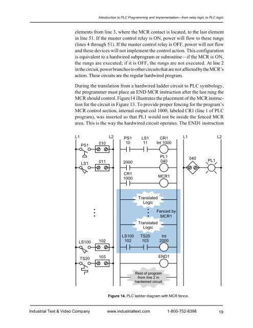
Introduction to PLC Programming <strong>and</strong> <strong>Implementation</strong>—from relay logic to PLC logicelements from line 3, where the MCR contact is located, to the last elementin line 51. If the master control relay is ON, power will flow to these rungs(lines 4 through 51). If the master control relay is OFF, power will not flow<strong>and</strong> these devices will not implement the control action. This configurationis equivalent to a hardwired subprogram or subroutine—if the MCR is ON,the rungs are executed; if it is OFF, the rungs are not executed. At line 2in the circuit, power branches to other circuits that are not affected by the MCR’saction. These circuits are the regular hardwired program.During the translation from a hardwired ladder circuit to PLC symbology,the programmer must place an END MCR instruction after the last rung theMCR should control. Figure14 illustrates the placement of the MCR instructionfor the circuit in Figure 13. To provide proper fencing for the program’sMCR control section, internal output coil 1000, labeled CR1 (line 1 of PLCprogram), was inserted so that PL1 would not be inside the fenced MCRarea. This is the way the hardwired circuit operates. The END1 instructionL1 L2 PS1 LS1 CR1 L1 L2PS1010 10 11 Int 1000LS10112000PL1040040PL1CR11000MCR1TranslatedLogicFenced byMCR1TranslatedLogicLS100102LS100102TS20103Int2000TS20 103END1Rest of programfrom line 2 inhardwired circuitFigure 14. PLC ladder diagram with MCR fence.Industrial Text & Video Company www.industrialtext.com 1-800-752-839819


