

Programmable Controllers: Theory and Implementation
Programmable Controllers: Theory and Implementation
Programmable Controllers: Theory and Implementation
- No tags were found...

You also want an ePaper? Increase the reach of your titles
YUMPU automatically turns print PDFs into web optimized ePapers that Google loves.
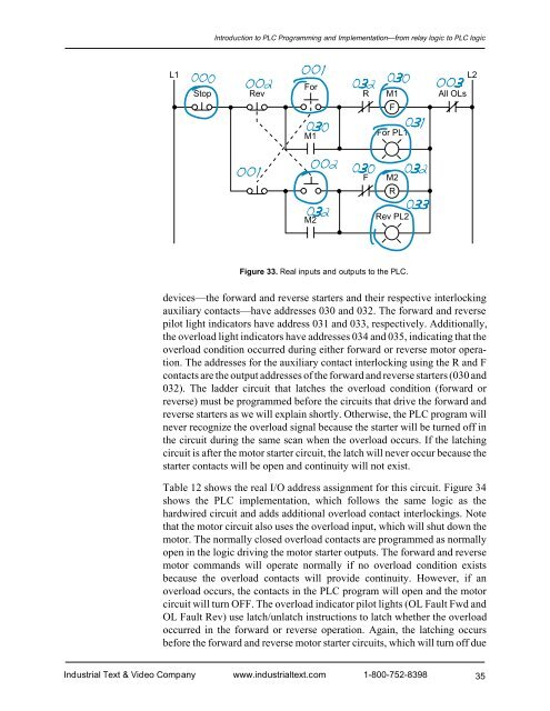
Introduction to PLC Programming <strong>and</strong> <strong>Implementation</strong>—from relay logic to PLC logicL1ForStop Rev R M1FAll OLsL2M1For PL1FM2RM2Rev PL2Figure 33. Real inputs <strong>and</strong> outputs to the PLC.devices—the forward <strong>and</strong> reverse starters <strong>and</strong> their respective interlockingauxiliary contacts—have addresses 030 <strong>and</strong> 032. The forward <strong>and</strong> reversepilot light indicators have address 031 <strong>and</strong> 033, respectively. Additionally,the overload light indicators have addresses 034 <strong>and</strong> 035, indicating that theoverload condition occurred during either forward or reverse motor operation.The addresses for the auxiliary contact interlocking using the R <strong>and</strong> Fcontacts are the output addresses of the forward <strong>and</strong> reverse starters (030 <strong>and</strong>032). The ladder circuit that latches the overload condition (forward orreverse) must be programmed before the circuits that drive the forward <strong>and</strong>reverse starters as we will explain shortly. Otherwise, the PLC program willnever recognize the overload signal because the starter will be turned off inthe circuit during the same scan when the overload occurs. If the latchingcircuit is after the motor starter circuit, the latch will never occur because thestarter contacts will be open <strong>and</strong> continuity will not exist.Table 12 shows the real I/O address assignment for this circuit. Figure 34shows the PLC implementation, which follows the same logic as thehardwired circuit <strong>and</strong> adds additional overload contact interlockings. Notethat the motor circuit also uses the overload input, which will shut down themotor. The normally closed overload contacts are programmed as normallyopen in the logic driving the motor starter outputs. The forward <strong>and</strong> reversemotor comm<strong>and</strong>s will operate normally if no overload condition existsbecause the overload contacts will provide continuity. However, if anoverload occurs, the contacts in the PLC program will open <strong>and</strong> the motorcircuit will turn OFF. The overload indicator pilot lights (OL Fault Fwd <strong>and</strong>OL Fault Rev) use latch/unlatch instructions to latch whether the overloadoccurred in the forward or reverse operation. Again, the latching occursbefore the forward <strong>and</strong> reverse motor starter circuits, which will turn off dueIndustrial Text & Video Company www.industrialtext.com 1-800-752-839835


