

Programmable Controllers: Theory and Implementation
Programmable Controllers: Theory and Implementation
Programmable Controllers: Theory and Implementation
- No tags were found...

Create successful ePaper yourself
Turn your PDF publications into a flip-book with our unique Google optimized e-Paper software.
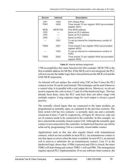
Introduction to PLC Programming <strong>and</strong> <strong>Implementation</strong>—from relay logic to PLC logicDeviceInternalDescriptionCR11000CR1 (Setup Rdy)TDR12000Timer preset 10 sec register 3000 (accumulatedregister 3001)MCRMCR1700First MCR addressC R2 — Same as PL3 addressC R3 — Same as PL4 addressC R4 — Same as SOL1— 1001To set up internal for instantaneous contact ofTDR2TDR22001Timer preset 5 sec register 4002 (accumulatedregister 4003)— 1002To set up internal for instantaneous contact ofTDR3TDR32002Timer preset 12 sec register 4004 (accumulatedregister 4005)Table 21. Internal address assignment.1700 accomplishes this same function (for this example, MCR1700 is thefirst available address for MCRs). If the MCR coil is not energized, the PLCwill not execute the ladder logic that is fenced between the MCR coil <strong>and</strong> theEND MCR instruction.An internal will not replace the control relay CR2 in line 9 since the PL3contacts in line 10 can be used instead. This technique can be used whenevera control relay is in parallel with a real output device. Moreover, we do notneed to separate the coils in lines 17 <strong>and</strong> 18 of the hardwired logic. This hasalready been done, since the PLC used here does not allow rungs withmultiple outputs. Using separate rungs for each output is always a goodpractice.The normally closed inputs that are connected to the input modules areprogrammed as normally open, as explained in the previous sections. Thelimit switch LS4 has two contacts—a normally open one <strong>and</strong> a normallyclosed one in lines 17 <strong>and</strong> 19, respectively, of Figure 45. However, only oneset of contacts needs to be connected to the controller. In this example, wehave selected the normally closed contact LS4. Although the normally opencontact is not connected to the controller, its hardwired function can still beachieved by programming LS4 as a normally closed ladder contact.Applications such as this one also require timers with instantaneouscontacts, which are not available in most PLCs. An instantaneous contact isone that opens or closes when the timer is enabled. In most PLCs, an internalcoil is used as a substitute for an instantaneous contact. Line 15 in thehardwired logic shows that, if PB6 is pressed <strong>and</strong> CR4 is closed, the timerTDR2 will start timing <strong>and</strong> contact TDR2-1 will seal PB6. This arrangementrequires special PLC implementation. If we use software timer contacts, theIndustrial Text & Video Company www.industrialtext.com 1-800-752-839850


